
Definition
What Is a Battery Simulator?
A battery simulator is test equipment that reproduces battery terminal behavior under controlled conditions. Instead of waiting for a real cell or pack to reach a specific state of charge, an engineer can set the voltage, current limits, internal-resistance behavior, or test profile needed for a charger, BMS, or electronic device.
In practical engineering use, the term can describe a single-channel battery emulator, a multi-channel cell simulator, or a larger pack-level simulator. The common purpose is repeatability: the device under test sees battery-like electrical behavior without the setup time and safety variability of a live battery in every early test.
When to Use a Battery Simulator vs a Real Battery
Real batteries remain essential for final validation and characterization work where electrochemical dynamics matter. However, simulators are preferred during early development, regression testing, and boundary-condition exploration because they offer deterministic control over terminal parameters. A simulator can hold exactly 3.400 V indefinitely, whereas a real Li-ion cell drifts with temperature, aging, and self-discharge. This determinism reduces test variability and allows engineers to isolate DUT behavior from battery-state uncertainty. For more on selecting specific hardware, see the battery simulator test equipment guide.
Current direction
Source and Sink Current Modes
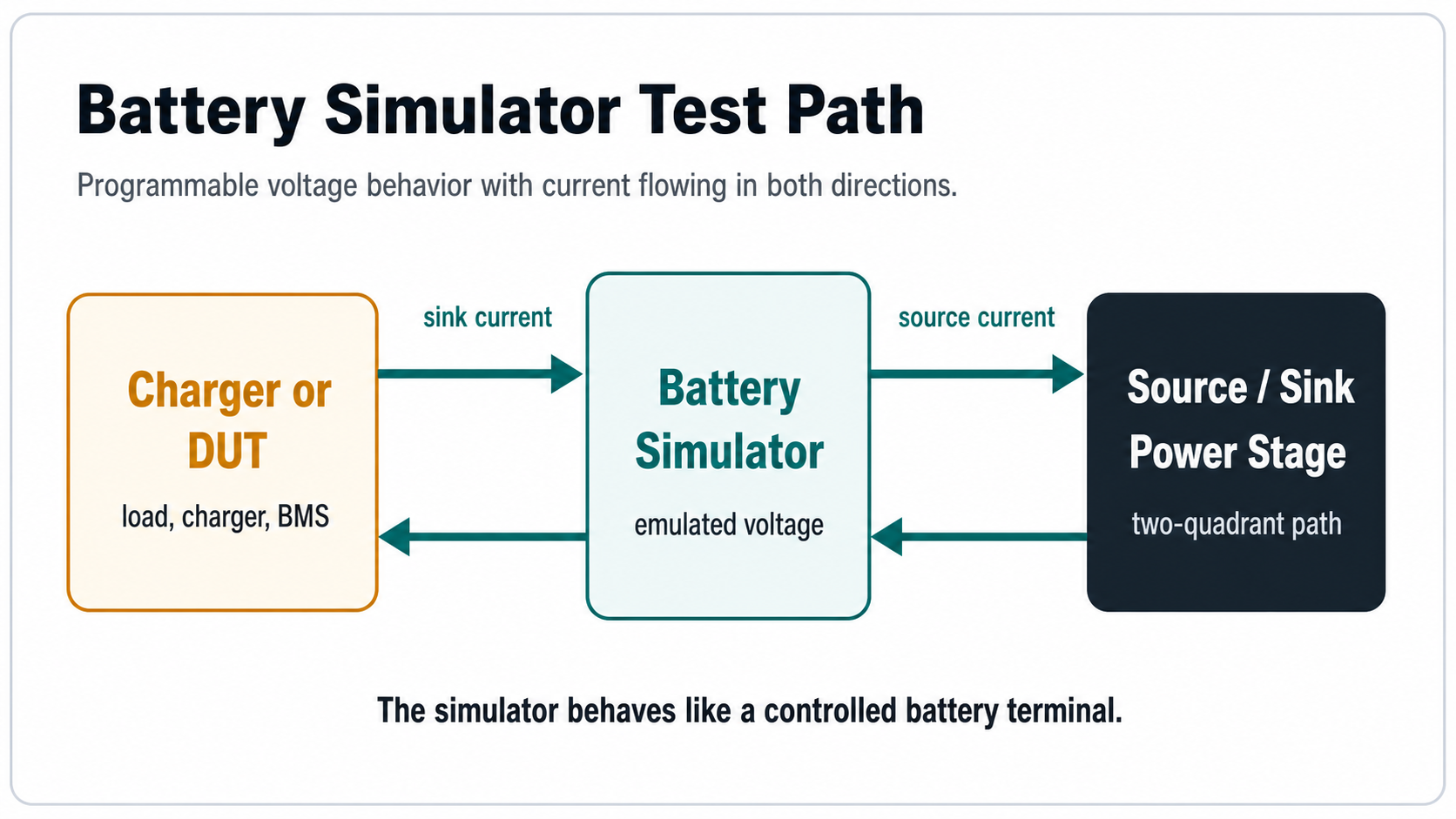
A battery terminal may deliver current to a load or accept current from a charger. For a simulator to behave like that terminal, it must support both directions of current flow. Understanding when each mode activates is essential for configuring tests correctly and avoiding unexpected shutdowns due to mode crossover.
The simulator delivers current while maintaining the programmed battery voltage, similar to a battery discharging into a load. This mode is active whenever the device under test draws power from the simulator — for example, a BMS waking up and drawing quiescent current, a DC-DC converter starting up, or any powered electronic load connected across the simulator output.
The simulator accepts current pushed by a charger or regenerative device while controlling the emulated battery terminal voltage. This mode is critical for charger testing: the charger outputs current, and the simulator must absorb it while holding the programmed voltage constant rather than allowing the terminal to rise uncontrolled as it would with an open-circuit condition.
Practical Mode Transition Scenarios
In many real-world tests, the direction of current flow changes during a single test sequence. Consider a BMS validation test: when the BMS first powers on, it sources a small quiescent load from the simulator (source mode). When an external charger connects and begins charging, current reverses and flows into the simulator (sink mode). If the BMS then enables a discharge path through a load bank, current direction flips back to source mode. A properly configured bidirectional simulator handles these transitions seamlessly without manual reconfiguration. Instruments limited to single-quadrant source-only operation require external load hardware to complete the same test, adding complexity and potential ground-loop issues.
This source-sink behavior is why battery simulators are often associated with two-quadrant or bidirectional DC power stages. A conventional source-only bench supply may power a load, but it is not sufficient for every charger or regenerative test because it cannot absorb returned current without additional circuitry. See the section below on quadrant operation for a detailed comparison of two-quadrant versus four-quadrant configurations.
Power stage topology
Two-Quadrant vs Four-Quadrant Operation
Quadrant terminology describes the combinations of voltage polarity and current direction a power electronic stage can support. For battery simulation, this determines whether the instrument can handle all operating conditions the DUT may produce.
Quadrant Definitions
- Quadrant I (+V, +I): Positive voltage, sourcing current — the simulator delivers power to a load, equivalent to a battery discharging.
- Quadrant II (+V, -I): Positive voltage, sinking current — the simulator absorbs current from a charger, equivalent to a battery being charged.
- Quadrant III (-V, -I): Negative voltage, sinking current — the simulator sinks current while presenting a negative terminal voltage relative to its reference.
- Quadrant IV (-V, +I): Negative voltage, sourcing current — the simulator sources current while presenting a negative terminal voltage.
Comparison Table
| Characteristic | Two-quadrant (Q1 + Q2) | Four-quadrant (Q1–Q4) |
|---|---|---|
| Voltage range | Positive voltage only (0 V to Vmax). | Bipolar voltage (-Vmax to +Vmax). |
| Current direction | Both source and sink at positive voltage. | Both source and sink at positive or negative voltage. |
| Typical use cases | Battery charger testing, BMS validation, standard EV/HV pack simulation where pack voltage never reverses. | Regenerative drive testing, inverter/motor-controller validation, bidirectional converter testing, fuel-cell stack simulation, applications with negative rail requirements. |
| Hardware complexity | Lower cost, simpler power stage design. | H-bridge or dual-stage output, higher component count, typically higher cost per watt. |
| Fault recovery | Limited to positive-voltage fault states. | Can simulate reverse-polarity faults, short-to-negative-rail conditions, and full bidirectional energy circulation. |
| Regeneration handling | Sinks energy as heat (dissipative) or returns to AC mains (regenerative), depending on model. | Same options plus ability to circulate energy internally in some architectures, improving efficiency in cyclic tests. |
For most battery-charger and BMS-validation applications, a two-quadrant simulator is sufficient because the emulated battery terminal voltage remains positive throughout the test cycle. Four-quadrant capability becomes necessary when the DUT itself can produce negative voltages — for instance, during inverter shoot-through events, motor regeneration into a DC bus that swings bipolar, or when testing automotive cranking scenarios with momentary voltage inversion. Engineers should match the quadrant rating to the actual DUT operating envelope rather than defaulting to four-quadrant hardware unnecessarily.
Comparison
Battery Simulator vs Conventional DC Power Supply
The distinction matters because many labs already own programmable DC supplies and need to understand whether those instruments are adequate for battery-emulation tasks or if dedicated simulator hardware is required.
| Capability | Conventional DC supply | Battery simulator |
|---|---|---|
| Primary role | Provide regulated voltage or current to a load. | Emulate battery terminal behavior for a device, charger, or BMS. |
| Current flow | Usually source current only. Some models add electronic load function but often as a separate channel or mode requiring reconfiguration. | May source and sink current simultaneously in a single output channel, with seamless transition between modes. |
| Charger testing | Limited unless paired with external electronic load or sink hardware. Requires manual setup change or second instrument. | Can absorb charger current while holding a battery-like voltage in a single integrated operation. No secondary instrument needed for basic CC/CV charger validation. |
| Battery behavior | Simple voltage/current regulation with optional list/arbitrary waveform programming. No inherent model of internal resistance, OCV-SOC curve, or thermal effects unless externally scripted. | May include built-in battery models: voltage profiles, internal resistance (static or dynamic), SOC-dependent OCV curves, temperature coefficients, capacity fade, and predefined fault states (open circuit, short circuit, overvoltage, undervoltage). |
| Dynamic response | Optimized for steady-state regulation bandwidth. Transient response specified but not tuned specifically for battery-load-step emulation (e.g., sudden load current change mimicking motor inrush). | Tuned for fast transient response to emulate battery terminal behavior during pulsed loads, including dV/dt characteristics that approximate real cell dynamics. Bandwidth specifications often prioritize step-response settling time relevant to battery-load profiles. |
| Programming interface | SCPI, LXI, analog, front panel. Profiles usually limited to voltage/current lists. | May include battery-specific APIs: set chemistry type, configure cell count, program SoC trajectory, define resistance profile, trigger fault injection sequences. |
| Safety integration | Standard OVP, OCP, OTP. May lack battery-specific protections such as cell-level monitoring or isolation fault detection. | May support isolated channels for multi-cell simulation, per-channel fault reporting, and integration with BMS HIL testing frameworks where safety-state feedback is part of the closed loop. |
If a lab already owns a programmable DC supply with a built-in electronic load function (sometimes marketed as a "bidirectional power supply"), it may cover basic charger testing for lower-power applications. However, dedicated battery simulators differentiate themselves through battery-model fidelity, faster mode-transition latency, multi-channel isolation for cell-level emulation, and tighter integration with automated test sequences that cycle through SoC boundaries. See also: Battery Emulator vs Battery Simulator.
Cell characteristics
Common Battery Chemistry Voltage Ranges
Selecting the correct voltage range for a battery simulator starts with understanding the target chemistry's open-circuit voltage (OCV) window. Each lithium-ion chemistry has a distinct nominal voltage, minimum cutoff voltage, and maximum charge termination voltage. Configuring the simulator outside these ranges produces unrealistic test conditions that can mask bugs or cause false failures in the DUT.
Lithium-Ion Chemistry Reference
Nominal: 3.2 V/cell. Operating range typically 2.5 V (discharge cutoff) to 3.65 V (charge termination). Very flat OCV curve over most of the SoC range makes voltage-based SoC estimation challenging. Common in stationary storage, e-buses, and cost-sensitive EV applications. Lower energy density than oxide cathode chemistries but superior cycle life and thermal stability.
Nominal: 3.6–3.7 V/cell (varies by Ni ratio). Operating range roughly 2.8–3.0 V (cutoff) to 4.20 V (standard charge) or 4.35 V (high-voltage variants). The dominant chemistry for consumer electronics and passenger EVs. Higher energy density than LFP, moderate cycle life. NMC 811 formulations push nickel content higher for increased capacity at the expense of thermal stability margins.
Nominal: 3.6 V/cell. Operating range approximately 2.5–3.0 V (cutoff) to 4.20 V (charge termination). Used primarily in high-energy-density applications including certain EV packs and aerospace. Similar energy density to NMC but with different aging and thermal runaway characteristics. More sensitive to overcharge conditions than LFP or standard NMC.
Nominal: 3.7 V/cell. Operating range 3.0 V (cutoff) to 4.35–4.40 V (charge termination for some high-capacity grades). Historically the standard for smartphones and laptops, now partially displaced by NMC in higher-demand applications. High volumetric energy density but limited cycle life compared to LFP. Strict voltage ceiling tolerance required during testing.
Nominal: 2.4 V/cell. Operating range 1.5–1.8 V (cutoff) to 2.85 V (charge termination). Exceptional cycle life (often rated >10,000 cycles), wide operating temperature range, and excellent charge acceptance. Used in industrial vehicles, grid buffering, and low-temperature applications. Requires simulator voltage range compatible with lower nominal values than standard Li-ion.
Nominal: ~3.0–3.1 V/cell. Operating range varies by formulation, roughly 1.5–2.0 V (cutoff) to 3.8–4.0 V (termination). Emerging alternative chemistry targeting stationary storage and cost-sensitive mobility. Hard-cathode versions reach higher voltages; soft-cathode versions operate at lower ceilings. Simulators intended for future-proofed test coverage should accommodate these ranges.
Pack-Level Voltage Calculation
For series-connected packs, multiply the per-cell voltage by the cell count. A 100S NMC pack has a nominal voltage of approximately 360–370 V, with a charge-termination voltage near 420 V and a discharge-cutoff around 280–300 V depending on the specific cell grade and end-of-life margin. The simulator's voltage span must cover this entire window with headroom for transient overshoot during fast current transitions. Underspecifying voltage range forces the engineer to test at non-representative voltages; overspecifying increases cost and may sacrifice resolution or accuracy at the actual operating band. See test equipment selection guidance for detailed sizing criteria.
Measurement accuracy
Kelvin (4-Wire) Sensing in Battery Simulation
Voltage measurement accuracy at the device-under-test terminals is one of the most frequently underestimated aspects of battery simulation. A simulator that reports 3.650 V at its output binding posts may present a significantly different voltage at the DUT input terminals due to voltage drop across cables, connectors, contact resistance, and distribution impedance.
The Problem with Two-Wire Connections
In a two-wire (local-sense) configuration, the regulator senses voltage at its own output terminals and compensates for internal drops within the instrument. However, it cannot compensate for voltage drop in the external cabling between the instrument and the DUT. With a 10 A charge current flowing through a total loop resistance of just 10 mOhm (realistic for long cable runs, connector pairs, and relay contacts), the IR drop is 100 mV. If the simulator regulates to 3.650 V locally, the DUT sees only 3.550 V — a 100 mV error that shifts the apparent SoC, alters charge-profile transition points, and potentially causes premature charge termination or failure to detect overvoltage conditions during BMS validation.
How Kelvin Sensing Solves It
Kelvin (4-wire) sensing separates the voltage measurement path from the current-carrying path. High-current force connections carry the charge/discharge current between the simulator output and the DUT. Separate sense connections carry negligible current (typically nanoamps to microamps into a high-impedance ADC input) and connect directly to the DUT input terminals or as close to them as physically possible. Because essentially zero current flows in the sense leads, there is no meaningful IR drop along them, and the regulator measures the true voltage at the point of interest. The regulator then adjusts its force output upward or downward to compensate for all drop in the force-path cabling, maintaining the programmed voltage at the DUT terminals regardless of current magnitude.
Implementation Guidelines
- Connect sense leads at the DUT terminals (or the closest accessible point to the DUT input), not at the simulator binding posts. Connecting sense leads at the simulator defeats the purpose of remote sensing.
- Use twisted pairs or shielded cable for sense leads to reduce noise pickup, especially in test environments with switching converters or motor drives nearby. Keep sense leads physically separated from force leads where feasible.
- Verify sense-lead integrity before running precision tests: an open sense lead causes the regulator to drive to maximum output (or compliance limit) attempting to reach the setpoint, which can damage the DUT.
- For multi-cell simulators with individual channel sensing, ensure each channel's sense connection reaches the corresponding cell-level test point. Cross-wiring sense channels produces incorrect per-cell voltage readings even if the aggregate pack voltage appears correct.
- Account for the voltage difference between the sense point and the actual cell terminal when using intermediate fixtures, relays, or switch matrices. Every interposing contact adds resistance that Kelvin sensing at the fixture output does not compensate for if the DUT connects beyond that point.
For typical BMS validation work, Kelvin sensing improves terminal-voltage accuracy from the range of 10–50 mV error (two-wire, at multi-ampere currents) to 1–2 mV or better, limited primarily by the instrument's own sense-input offset and ADC resolution. This improvement is not academic: BMS overvoltage and undervoltage protection thresholds commonly sit 50–200 mV away from normal operating voltage, so a 50 mV measurement error can shift the apparent trip point by 25–100% of the design margin.
Configuration
Compliance Voltage and Range Selection
Every battery simulator operates within a defined voltage and current envelope. Understanding how compliance voltage, programmed voltage, and current limits interact prevents test aborts, unexpected mode transitions, and equipment damage.
Compliance Voltage Defined
The compliance voltage is the maximum voltage the instrument will reach while operating in constant-current (CC) mode. When the simulator is sinking current from a charger programmed for constant-current charging, the simulator holds the programmed battery voltage. However, if the charger's output voltage (open-circuit) exceeds the simulator's compliance setting, or if the simulator hits an internal voltage ceiling, the instrument transitions out of regulation and either clamps, trips, or switches behavior depending on its architecture. In a well-configured test, the compliance voltage is set comfortably above the highest expected emulated battery voltage but below any DUT absolute-maximum rating that the test is intended to validate against.
Selection Criteria
For an NMC cell test, the simulator must reach at least 4.35 V (or 4.40 V for high-voltage grades) to represent a fully charged cell, and extend down to 2.5–3.0 V for deep-discharge scenarios. Select an instrument whose full-scale range brackets the chemistry's entire operating window plus margin for transients.
A 12S LFP pack terminates at 43.8 V (12 x 3.65 V) and cuts off around 30 V (12 x 2.5 V). A 100S NMC pack requires 420 V+ headroom. Ensure the simulator's maximum voltage rating exceeds the pack's highest expected charge-termination voltage by at least 10–15% to accommodate regulation overhead and transient overshoot.
An instrument with a 0–60 V range and 16-bit DAC resolution offers approximately 0.9 mV/LSB. The same DAC spread over 0–600 V gives 9 mV/LSB. For cell-level simulation where millivolt accuracy matters, choose the lowest range that still covers the required voltage window, or verify that the instrument provides range-switching or zoom capability.
Common Configuration Errors
- Setting compliance too low: The simulator hits its voltage ceiling during constant-current charging, causing the terminal voltage to rise above the programmed value and potentially triggering a false overvoltage fault in the BMS under test. The test result becomes invalid because the DUT responded to an unregulated condition rather than a stable battery emulation.
- Setting compliance too high without OVP coordination: If the simulator can output 500 V but the DUT's absolute maximum is 450 V, a software bug or misconfiguration that drives the simulator toward its maximum can damage the DUT before any external protection intervenes. Always configure the simulator's independent overvoltage protection (OVP) threshold below the DUT's absolute-maximum rating, separate from the normal operating compliance setting.
- Ignoring cold-start and precharge conditions: Many systems apply a precharge sequence before connecting the main battery contactor. The simulator must correctly represent the precharge voltage ramp and the transition to nominal pack voltage. An incorrectly ranged simulator may clip the precharge ramp or fail to hold the intermediate voltage, causing the BMS to report a precharge timeout fault that does not occur with a real battery.
Workflow
Battery Charger Testing Workflow
Charger testing is the most common application for battery simulators with sink capability. The goal is to verify that the charger correctly implements its charge algorithm (typically CC-CV or a variant), transitions between modes at the correct thresholds, terminates appropriately, and responds correctly to fault conditions — all without requiring a physical battery at each test state.
Step-by-Step Test Procedure
- Configure the emulated battery voltage. Set the simulator to represent the desired battery state: a deeply discharged voltage (e.g., 3.00 V/cell for NMC), a mid-SoC nominal voltage (~3.70 V/cell), or a near-full voltage approaching charge termination (e.g., 4.15 V/cell). If the simulator supports battery modeling, select the appropriate chemistry profile and set the target SoC or OCV value directly.
- Configure current and protection limits. Set the simulator's sink current limit to at least the charger's maximum expected output current plus margin. Configure the simulator's OVP threshold above the expected CV phase voltage but below the DUT's absolute-maximum rating. Enable any data logging or oscilloscope triggering on the simulator's voltage and current outputs so transients during mode transitions are captured.
- Connect the charger or device under test. Wire the charger output to the simulator input using Kelvin (4-wire) connections wherever possible. Verify wiring polarity, confirm sense-lead attachment points, and check that the simulator's remote-sense mode is enabled. The charger should now recognize the simulator as the battery terminal it is designed to charge.
- Initiate charging and observe CC phase. Start the charger. In the constant-current phase, the charger delivers its programmed charge current (e.g., 1C rate), and the simulator absorbs this current while holding the programmed battery voltage. Record the actual current delivered, the terminal voltage stability, and any ripple or noise superimposed on the DC level. Compare measured values against the charger specification sheet.
- Monitor CV phase transition and termination. As the emulated battery voltage approaches the charger's voltage setpoint (which may or may not equal the simulator's programmed voltage, depending on test intent), the charger should transition from CC to CV mode. In CV mode, current decays exponentially (for resistive-loaded simulations or simple voltage-hold models) according to the charger's control loop. Verify that the taper current threshold and termination timer behave as specified.
- Repeat at boundary conditions. Cycle through the full matrix of test voltages: minimum start-of-charge voltage, nominal midpoint, and near-termination voltage. Test at hot and cold ambient temperatures if the simulator and chamber support it. Test at the charger's minimum, nominal, and maximum input-voltage conditions. Each combination represents a corner case where implementation bugs in the charger firmware often surface.
- Test fault-response behavior. Using the simulator's fault-injection capability (if available) or manual voltage adjustment, simulate conditions such as battery disconnect (simulator output disabled/open), overvoltage (simulator driven above normal termination voltage), and short circuit (simulator briefly set to very low impedance). Confirm that the charger enters the correct protective state (shuts down, flags a fault, retries after delay) and recovers normally when the condition clears.
Data Points to Capture Per Test Run
Charge current magnitude and stability (ripple, deviation from setpoint), time spent in CC mode, terminal voltage during CC phase (should remain near the programmed emulated voltage until CV transition point).
Transition voltage (where CC-to-VT switch occurs), taper-current decay curve shape and time constant, termination current threshold accuracy, total termination time, final float voltage.
OVP trigger voltage and response time, response to simulated open-circuit and short-circuit conditions, restart behavior after fault clearing, any unexpected oscillations or mode chatter near threshold boundaries.
Applications
Common Engineering Use Cases
Check sensing accuracy, cell balancing logic, protection thresholds (OVP, UVP, OCP, OTP), communication protocol handling, and state-machine transitions before committing to real-battery validation. Simulators allow rapid iteration through thousands of fault-injection scenarios that would take weeks with physical cells.
Measure charger response across simulated voltage and current boundary conditions. Validate CC-CV algorithms, input-voltage foldback behavior, efficiency maps, and thermal-management interactions. Simulators eliminate the wait time for cycling real batteries between test states.
Provide controlled battery-like behavior for DC-DC converters, motor controllers, inverters, and embedded power-management ICs. Emulate startup inrush, load transients, and regeneration events with deterministic repeatability for regression testing and design verification.
Frequently asked questions
FAQ
What is a battery simulator?
A battery simulator is a programmable test instrument or system that reproduces battery terminal behavior so a charger, BMS, or electronic device can be tested without relying only on a real battery.
Why does a battery simulator need source and sink current?
Source current lets the simulator power a device under test. Sink current lets it absorb current from a charger or regenerative device, which is needed when the equipment being tested pushes current back into the simulated battery.
How is a battery simulator different from a conventional DC power supply?
A conventional DC power supply usually sources current to a load. A battery simulator used for charger testing may also need sink capability, so it can absorb current while maintaining a programmed battery voltage. Additionally, dedicated battery simulators provide built-in battery models (OCV-SoC curves, internal resistance, temperature coefficients) that conventional supplies lack unless manually scripted.
What is the difference between two-quadrant and four-quadrant operation?
Two-quadrant operation means the instrument operates at positive voltage (Quadrants I and II) while sourcing or sinking current. Four-quadrant operation adds negative-voltage capability (Quadrants III and IV), which is required when testing bidirectional systems such as regenerative drives or inverter-fed loads where voltage polarity reverses during braking or fault conditions. For standard battery charger and BMS testing where the emulated terminal voltage stays positive, two-quadrant operation is typically sufficient.
Why is Kelvin (4-wire) sensing important for battery simulation?
Kelvin (4-wire) sensing separates the voltage sense leads from the high-current force leads, eliminating errors from cable and contact resistance. For battery simulation where terminal voltage accuracy directly affects BMS SoC estimation, protection-threshold validation, and charge-profile verification, this separation typically improves measurement accuracy from tens of millivolts to sub-millivolt levels at the DUT terminals. Without remote sensing, IR drop in test fixtures and cabling introduces voltage errors that shift the effective test condition away from the intended setpoint.