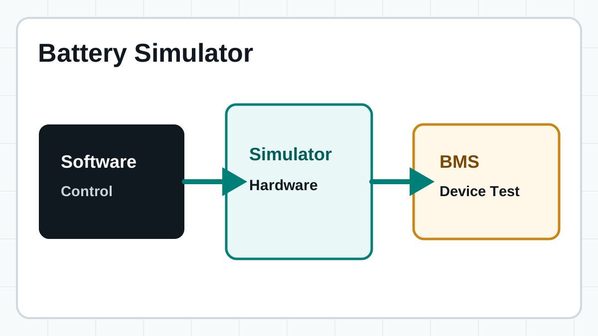
Reproduce normal cells, imbalance, voltage boundaries, and fault states while checking BMS logic. Simulate over-voltage, under-voltage, over-temperature, and open-wire conditions to verify that the BMS triggers protection at the correct thresholds. Run automated regression test suites that would be impractical with real batteries.
Core topic guide
Battery Simulator
A battery simulator reproduces battery behavior under controlled conditions so engineers can test BMS hardware, power electronics, protection logic, and automation workflows before moving to real battery packs.
- Programmable battery behavior for engineering benches
- Cell and pack simulation paths
- Useful before final real-battery validation
Short answer: a battery simulator is hardware, usually software-controlled, that acts like a battery for the device under test. Depending on the test requirements, this can range from multi-channel battery cell simulators for individual cell monitoring, to full-scale battery pack simulators for high-voltage battery packs. It helps teams validate behavior repeatedly, safely, and earlier than a real battery-only workflow allows. The core value is deterministic, repeatable test conditions: every engineer on the team sees the same cell voltages, the same SOC states, and the same fault scenarios, which is impossible with physical batteries that age and drift between test runs.
Internal architecture
How a Battery Simulator Works
A battery simulator converts digital battery models into physical voltage and current that a device under test (DUT) can sink or source. The architecture combines precision digital-to-analog conversion, power amplification, and closed-loop feedback to maintain accurate output even as the load changes dynamically.
Digital-to-Analog Conversion (DAC) Stage
At the core, the control software computes what voltage and current each simulated cell should produce at a given moment. These setpoints are passed to a high-resolution DAC — typically 16-bit or 18-bit — that converts the digital value into a low-level analog reference voltage. The DAC resolution directly determines the minimum voltage step the simulator can output; a 16-bit DAC across a 5 V range yields approximately 76 µV per step, which is sufficient for most BMS validation tasks. Higher-end simulators use 18-bit or 20-bit DACs for sub-100 µV resolution across wider voltage ranges.
Power Amplifier and Output Stage
The DAC reference signal alone cannot drive a BMS input or power electronics load. A linear or switching power amplifier stage scales the reference to the required output level and provides the current sourcing and sinking capability the DUT demands. Linear output stages offer lower noise and faster transient response — critical for simulating sharp cell voltage transitions during fault injection. Switching stages are more common in higher-power pack-level simulators where efficiency is a concern. Galvanic isolation between channels is built into this stage to prevent ground loops from corrupting measurements when simulating series-connected cell strings.
Closed-Loop Feedback and Sensing
The amplifier output is continuously monitored by an ADC-based sense circuit that measures actual voltage and current at the DUT terminals. This measurement is fed back to the control loop, which compares it against the commanded setpoint and corrects any deviation — compensating for cable voltage drops, load transients, and thermal drift. The feedback bandwidth determines how quickly the simulator can respond to load changes. For BMS passive balancing tests, where the BMS draws brief pulses to bleed individual cells, the simulator must track and maintain setpoint voltage within hundreds of microseconds. Lower-bandwidth simulators may sag during these pulses, producing misleading balancing results.
Use cases
Where Battery Simulators Fit
Battery simulators are useful when battery behavior must be controlled rather than discovered after a pack is already connected. They replace the variability of real cells with deterministic, programmable conditions across the full operating envelope.
Use programmable outputs to evaluate DC-DC converters, onboard chargers, inverters, and motor controllers. A battery simulator lets engineers test edge cases — such as minimum input voltage brownout or full-load transients — without risking an actual battery pack or waiting for it to reach a specific SOC.
Build sequences for repeated validation, engineering handoff, and production-oriented test benches. Integrate with battery simulator software to script test campaigns, log results, and generate pass/fail reports. This is essential for manufacturing lines where every BMS must be verified against identical battery profiles.
Terminology
Battery Simulator, Emulator, and Cycler
| Term | Meaning in practice | Best fit | Limit |
|---|---|---|---|
| Battery simulator | Broad term for equipment that reproduces battery behavior. | General battery-like testing and BMS benches. | Meaning varies by supplier and project. |
| Battery emulator | Often used for precise programmable reproduction of cell or pack behavior. | Early validation, repeatable conditions, and fault testing. | Does not replace final safety testing. |
| Battery cycler | Charges and discharges real cells or packs over cycles. | Performance, aging, capacity, and cycling data. | Requires real batteries and longer test time. |
Classification
Battery Simulator Types
Battery simulators are designed at different levels of the system hierarchy. Selecting the right type depends on whether the test target is an individual cell monitoring channel, a full BMS, or a complete powertrain.
| Type | Voltage range | Channel count | Typical use | Example |
|---|---|---|---|---|
| Cell-level simulator | 0–5 V per channel | 12–120+ channels | BMS cell monitoring IC validation, balancing tests, fault injection | FT8330 Series |
| Pack-level simulator | 0–1000 V | Single channel, high-current | Pack-level BMS testing, contactor sequencing, isolation monitoring | FT8350 Series |
| Modular simulator | Configurable per module | Scalable by adding modules | Systems that need to grow from cell to pack testing on one platform | FT8340 configuration |
Selection criteria
Key Specifications to Evaluate
When selecting a battery simulator for BMS validation, several electrical and functional specifications determine whether the instrument can produce meaningful test results. Prioritize the parameters that match your specific test requirements rather than chasing the highest numbers across the board.
- Voltage accuracy: Typically ±1 mV per channel for cell-level simulators. This matters most when validating BMS voltage measurement accuracy — if the simulator has ±5 mV error and the BMS specification requires ±2 mV, the test cannot discriminate between simulator error and BMS error.
- Voltage setpoint resolution: 100 µV or better. Determines the smallest voltage step the simulator can produce when ramping between SOC levels or simulating aging effects.
- Current sourcing and sinking capability: Cell simulators must sink the balancing current the BMS draws during passive balancing (typically 50–200 mA per channel). Insufficient sinking capacity causes voltage to drift, corrupting balancing test results.
- Channel-to-channel isolation: At least 500 V DC between channels for series-string simulation. Without proper isolation, leakage currents between channels can produce false voltage readings and defeat the purpose of simulating independent cells.
- Response time / feedback bandwidth: The closed-loop control bandwidth determines how fast the simulator recovers from load steps. For BMS passive balancing tests, bandwidth above 10 kHz is recommended so the output voltage recovers within tens of microseconds after a balance pulse.
- Output noise and ripple: RMS noise below 1 mV is typical for cell-level channels. Excess noise masks the BMS measurement and can cause false ADC readings.
- Fault injection capability: Look for open-wire simulation, short-circuit to adjacent channel, short to GND, and reversed polarity. The best simulators let you trigger each fault per channel through the battery simulator software without rewiring.
- Remote sense (4-wire Kelvin connection): Compensates for voltage drop in test leads. When running dozens of channels to a BMS connector, cable resistance can add several millivolts of error that remote sense eliminates.
FaithTech paths
Battery Simulator Product Directions
For multi-channel cell-string simulation, voltage options, fault simulation, and BMS validation workflows.
For projects that need bidirectional behavior, balancing tests, and automated BMS benches.
For teams that need a full path from cell emulation to signal validation, fault checks, and reporting.
Comparison
Battery Simulator vs Real Battery
Battery simulators and real batteries serve different purposes in the development lifecycle. Understanding when to use each — and when to use both — avoids wasted effort and missed test coverage.
| Aspect | Battery simulator | Real battery |
|---|---|---|
| Repeatability | Identical conditions every test run | Aging, temperature history, and SOC drift between runs |
| Fault testing | Safe injection of over-voltage, under-voltage, open-wire, short-circuit | Faults can damage the battery or create safety hazards |
| Test speed | Instant state changes; no charge/discharge wait time | Hours of cycling to reach target SOC or temperature |
| Edge case coverage | Every quadrant of the operating envelope on demand | Limited to what the physical cell can safely tolerate |
| Thermal behavior | Simulated via models; no physical heat | Actual thermal dynamics, mandatory for safety validation |
| Aging / degradation | Simulated through parameter changes | Real calendar and cycle aging, required for lifetime testing |
In practice, development teams use the simulator for 80–90% of BMS validation and reserve the real battery for final safety, thermal, and lifetime tests. A simulator cannot replace the last phase — but using one for everything before that phase reduces risk, speeds up development, and eliminates the cost of cycling real packs through thousands of functional test iterations.
Applications
Common Applications Beyond BMS Testing
While BMS validation is the primary use case, battery simulators support a range of adjacent test scenarios across the electrification ecosystem.
A programmable battery simulator lets charger manufacturers verify CC/CV transition points, pre-charge behavior, charge termination, and protection responses across multiple cell chemistries without maintaining a physical library of aged batteries at every SOC.
Pack-level simulators provide the DC link for inverter testing. Engineers can simulate battery voltage sag under load, regenerative braking energy return, and limp-home voltage profiles to validate inverter firmware response.
Many battery simulator test equipment platforms support user-defined V-I curves, enabling simulation of fuel cell stacks, supercapacitor banks, and other energy sources with non-linear terminal behavior for hybrid powertrain development.
Workflow
How to Set Up a Battery Simulator Test
Setting up a battery simulator for BMS validation follows a structured workflow. Each step builds on the previous one to produce a reliable, documented test environment.
- Define test requirements. List the number of cells in series, voltage range per cell, required accuracy, balancing current, and the fault states you need to simulate. This determines which simulator type and channel count you need.
- Select and configure hardware. Choose the appropriate simulator (cell-level, pack-level, or modular) and wire the channels to the BMS using the correct harness. Use 4-wire Kelvin connections where available to eliminate cable resistance errors. Verify channel-to-channel isolation before powering on.
- Install and configure software. Install the battery simulator software and load the battery model for your target chemistry — most platforms include pre-built models for common Li-ion chemistries (NMC, LFP, LTO). Configure SOC ranges, temperature compensation curves, and internal resistance profiles that match your target cell.
- Run baseline validation. Set all channels to nominal voltage and verify the BMS reads each channel correctly. Check that the BMS total pack voltage matches the sum of simulated cell voltages within the expected tolerance.
- Execute functional tests. Run the test sequence: simulate normal operation, introduce cell imbalance (set one cell 100 mV low), trigger over-voltage on one channel, inject an open-wire fault. Log all BMS responses at each step.
- Automate and document. Script the full test campaign for repeatable execution across firmware revisions. Export logs, compare against expected behavior, and generate pass/fail reports. Archive the test configuration so any engineer on the team can reproduce the exact conditions months later.
FAQ
Battery Simulator FAQ
What is a battery simulator?
It is a programmable system that reproduces battery behavior so electronics can be tested under controlled conditions. A battery simulator converts digital battery models into physical voltage and current, enabling engineers to validate BMS hardware, power electronics, and protection circuits without relying on physical batteries that vary between test runs.
Is a battery simulator software?
In practice, a battery simulator consists of physical hardware units controlled by specialized battery simulator software. The software provides the user interface to configure battery models, adjust State of Charge (SOC), run automated test sequences, simulate cell faults (like open wire or short circuit), and record logs, while the hardware generates the actual physical voltages and currents.
What is the difference between a battery simulator and a real battery?
A simulator is controlled and repeatable. A real battery is required for final safety and performance validation. The simulator excels at functional testing, fault injection, and regression testing where deterministic conditions matter. The real battery is necessary for thermal characterization, aging studies, and safety certification where physical electrochemistry cannot be substituted by a model. Most development programs use simulators for 80–90% of validation and reserve real batteries for the final phase.
Which products should I compare?
Compare FT8330, FT8331, FT8340, and FT8350 for cell simulation, and complete BMS testing solutions for broader benches. Cell-level products like the FT8330 and FT8331 Series target multi-channel BMS monitoring validation. The FT8340 and FT8350 Series address bidirectional testing and higher-power pack-level simulation. A complete BMS testing solution bundles hardware, software, and test scripts for turnkey deployment.
How does a battery simulator handle fault injection?
Advanced battery simulators inject faults on a per-channel basis through software commands. Common fault types include open-wire simulation (disconnecting a single cell sense line), short-circuit to adjacent channel, short-circuit to ground, over-voltage and under-voltage conditions, and reversed polarity. The key advantage is that these faults can be triggered and cleared instantly without physically rewiring the test setup, enabling automated fault coverage testing that would be hazardous or destructive with real batteries. The BMS must detect each fault and respond correctly — the simulator provides a safe, repeatable way to verify that logic.
What accuracy and resolution should I expect?
Cell-level simulators typically deliver voltage accuracy within ±1 mV and setpoint resolution down to 100 µV. Current measurement accuracy is typically ±0.05% of the measurement range. When evaluating a simulator, look beyond the headline accuracy: consider temperature drift specifications, long-term stability, output noise (RMS mV), and whether the accuracy spec holds across the full operating temperature range. For BMS validation where the BMS itself specifies ±2 mV measurement accuracy, the simulator should ideally be at least 3x better than that target to provide meaningful test margin.
Related guides
Explore More Battery Simulation Topics
Talk to FaithTech
Need a battery simulator for BMS testing?
Share your electrical range, channel count, fault cases, and automation plan. FaithTech can help match the right product or full test solution.