
A centralized architecture routes all cell sense wires to a single PCB. The simulator must provide channel-to-channel and channel-to-ground isolation rated for the full stack voltage. Channel count equals the series cell count (e.g., 96S for a 400V pack). Voltage accuracy must hold across the entire channel array under simultaneous load, since all channels drive the same BMS front-end ICs at once.
Equipment selection guide
Battery Simulator Test Equipment
Battery simulator test equipment helps engineers reproduce cell voltage, pack behavior, sensor conditions, and fault cases before using real batteries in BMS, EV, ESS, UPS, and robotics programs.
- Cell-level simulation for BMS validation
- Repeatable fault and imbalance scenarios
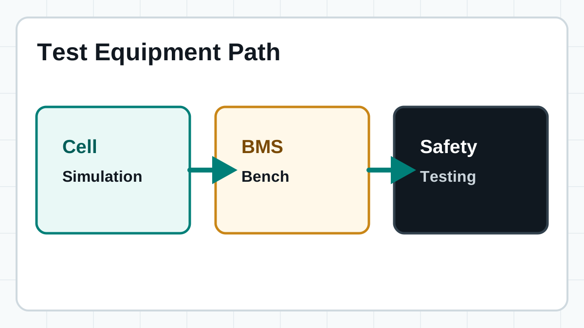
- Path from emulation to real battery safety testing
Short answer: battery simulator test equipment is a controlled test setup that makes a BMS or power electronics system believe it is connected to real cells or packs. It is used when teams need repeatable conditions, safer early validation, and faster fault testing than real batteries can provide. Different components can target specific needs, such as a multi-channel battery cell simulator for balancing verification, or a full-scale battery pack simulator for high-voltage system response checks. For a discussion on naming, see our battery emulator vs battery simulator comparison.
A complete test bench typically integrates several subsystems beyond the simulator itself: precision power sources, fault insertion units, communication interfaces, data acquisition hardware, and safety monitoring equipment. The BMS simulation workflow depends on this integration to produce repeatable, documentable results across development iterations. Engineers select equipment based on the specific battery topology, the validation stage they are in, and the regulatory standards their product must meet.
Component overview
What Constitutes a Complete Battery Simulator Test Equipment Setup
A production-grade test bench is more than a single instrument. It is an integrated system of hardware, software, and safety infrastructure that together reproduce the electrical and environmental conditions a BMS encounters in operation.
- Multi-channel battery cell simulator — Provides isolated, programmable voltage sources per series cell. Must support independent setpoints, series stacking for string emulation, and sink/source current for passive and active balancing validation. A battery cell emulator in this role must maintain voltage accuracy under varying load conditions.
- Pack-level simulator or high-voltage power supply — For systems where the BMS monitors total pack voltage directly, a separate high-voltage channel reproduces the aggregated string voltage with ground-referenced isolation from the cell-level channels.
- Fault simulation modules — Hardware or software-controlled relay matrices that insert open-circuit, short-circuit, reverse-polarity, and leakage faults at individual cell sense lines. These are critical for verifying BMS fault detection and protection response times.
- Sensor signal emulation — Programmable resistance outputs for thermistor simulation (NTC/PTC), current sensor emulation (Hall-effect or shunt-based), and insulation resistance simulation. These allow the BMS to be tested against its full sensor input range without physical sensors.
- Communication interface hardware — CAN, SPI, I2C, or isoSPI bus interfaces that connect the test bench to the BMS under test, enabling automated command sequences, register reads, and data logging synchronized with stimulus changes.
- Automation software and test scripting — A battery simulator software platform that orchestrates voltage profiles, fault sequences, data capture, pass/fail evaluation, and report generation across dozens or hundreds of test cases.
- Data acquisition (DAQ) and logging — Independent measurement channels that verify simulator output accuracy and capture BMS response waveforms, including cell voltage measurements, balancing currents, communication bus traffic, and digital I/O state changes.
- Safety interlock and emergency stop — Hardwired E-stop circuits, isolation monitoring, over-temperature sensors, and enclosure interlocks that protect operators and equipment when high voltages or fault injection are active.
BMS topology matters
How to Select Equipment Based on Your BMS Architecture
The BMS architecture directly determines which simulator capabilities are non-negotiable and which are optional. Matching equipment to architecture avoids over-specifying or under-specifying the test bench.
Distributed architectures split monitoring across multiple slave modules communicating via isoSPI or CAN. The simulator setup may use multiple independent cell simulator units, each assigned to one module. Communication timing and synchronization between simulator channels must match the module polling sequence. Channel isolation requirements are lower per module but must support the module-to-module voltage differential.
Wireless BMS architectures eliminate the wired isoSPI bus, replacing it with RF links per module. The simulator must inject controlled timing jitter and communication latency to test the BMS under real-world RF conditions. Additional test equipment includes spectrum analyzers for coexistence testing and channel emulators to simulate multi-path and interference scenarios.
How to choose
Match the Equipment to the Test Stage
Most projects do not need one universal tester. They need the right path for early BMS validation, system-level checks, and final safety work. Selecting the wrong equipment for a stage wastes budget and delays qualification timelines.
Use multi-channel isolated outputs to reproduce cell strings, imbalance, standby current, balancing behavior, and open or short cases. At this stage, a battery cell simulator with at least 12-bit voltage resolution and per-channel sink/source current capability is the minimum baseline for meaningful BMS AFE validation.
Combine cell emulation with signal validation, protection checks, communication, automation, and reporting workflows. The FT9350 comprehensive battery emulator provides an integrated path for cell, NTC temperature, total voltage/current, and controlled fault signals.
Move to pack-level charge, discharge, protection, thermal, and safety checks after emulation reduces early project risk. No simulator can fully replace the thermal runaway propagation, gas venting, and mechanical stress scenarios that real battery testing must validate.
Stages
Test Equipment for Different Validation Stages
Equipment requirements shift significantly across R&D, design validation, and production testing. A bench that works for firmware development may be inadequate for production-line throughput or DVT traceability requirements.
| Stage | Primary equipment | Key requirements | Typical test throughput |
|---|---|---|---|
| R&D / Firmware development | Multi-channel cell simulator, basic DAQ | Flexibility, scripting, quick reconfiguration; accuracy can be moderate if relative behavior is the focus | Low — interactive, exploratory testing |
| Design validation (DVT) | Full BMS test system with fault modules, environmental chamber | High accuracy, full traceability, automated regression suites, environmental stress (temperature/humidity cycling) | Medium — overnight regression runs |
| Production / End-of-line | High-speed cell simulator, fixture-integrated pin bed, MES interface | Fast channel settling, pass/fail in seconds, barcode/QR traceability, Manufacturing Execution System integration | High — seconds per DUT, thousands per day |
| Certification and compliance | Calibrated simulator, external reference meters, safety test systems | ISO 17025 traceable calibration, compliance with UN 38.3, IEC 62619, UL 1973; documented uncertainty budgets | Low — formal test campaigns per standard |
Comparison
Equipment Types Engineers Usually Compare
| Equipment | Best use | Typical questions it answers | FaithTech path |
|---|---|---|---|
| Battery cell simulator | Cell-level BMS validation | Will sensing, balancing, and fault logic behave correctly? | FT8330, FT8331, FT8340, FT8350 Series |
| Comprehensive battery emulator | Integrated BMS signal and fault validation | Can one platform coordinate cell, NTC, pack-level voltage/current, and fault inputs? | FT9350 Series |
| Battery pack simulator | Pack or system behavior | How does the controller react to pack-level voltage and current behavior? | BMS testing solution and related systems |
| Battery cycler | Charge and discharge performance | How does a real cell or pack perform over repeated cycles? | Use after simulation when real battery data is required |
| Safety test system | Real battery validation | Does the pack stay inside required safety boundaries? | FTS8500 and related safety systems |
Buy vs build
Off-the-Shelf vs Custom Test Equipment
Engineering teams often debate whether to purchase commercial simulator equipment or build custom benches from programmable power supplies and relay boards. The decision has lasting consequences for validation repeatability, calibration traceability, and team bandwidth.
Pre-built systems from vendors like FaithTech provide calibrated, isolated channels with documented accuracy specifications, built-in fault simulation, and supported automation APIs. They reduce integration time from months to days and come with manufacturer calibration certificates required for DVT and certification audits. The trade-off is higher upfront cost per channel compared to a DIY approach using general-purpose power supplies.
Teams assemble cell simulators from programmable DC power supplies, resistor dividers, relay matrices, and custom LabVIEW or Python control software. This path provides maximum flexibility for unusual topologies and can have lower capital cost. However, it demands significant internal expertise in isolation design, grounding schemes, and calibration verification. Long-term maintenance and documentation burden often exceeds initial expectations.
Many teams use a commercial multi-channel cell simulator as the core voltage source, then build custom fault injection boards, environmental sensor simulators, and automation wrappers around it. This balances the reliability and calibration of commercial hardware with the flexibility to add project-specific test conditions. The approach works well when the BMS topology is standard but the test sequences are unique.
Selection checklist
Key Specifications Checklist for Test Equipment Selection
Before requesting a quote or building a bench, confirm every parameter in this checklist against your product requirements document. Missed specifications at this stage cause rework, schedule delays, and budget overruns.
Define cell count, voltage range, output current, isolation needs, and whether the setup must handle bidirectional behavior. For N-series cells, confirm the simulator supports N independent channels with at least the max cell voltage per channel and sufficient common-mode isolation for the full stack voltage. Verify current sink/source ratings separately — passive balancing validation requires sinking current, while active balancing may require both directions simultaneously.
List the protection logic and abnormal states the BMS must see repeatedly during development. Confirm whether fault insertion is per-channel or global, whether short-circuit current is limited to safe levels, and whether the fault hardware can sequence multiple fault types in a single automated test run without manual rewiring.
Confirm interface requirements (SCPI, Python API, LabVIEW drivers, CAN/LIN scripting), automated sequence capabilities, data logging resolution and storage, and handoff to production or safety teams. Production environments add requirements for MES integration, barcode scanning triggers, and pass/fail logging with traceable test IDs.
Specify voltage accuracy (e.g., ±1mV or ±0.02% of setting), temperature coefficient over the operating range, output noise (RMS and peak-to-peak), and long-term drift. DVT and certification stages demand accuracy an order of magnitude better than what R&D benches typically provide. Confirm that the accuracy specification holds at the DUT sense point, not just at the simulator output terminals.
Verify isolation voltage ratings for both channel-to-channel and channel-to-ground, creepage and clearance compliance with IEC 61010 or IEC 62368, and whether the isolation scheme supports floating measurements required by some BMS AFE topologies. Stacked architectures with 800V or higher require reinforced isolation ratings.
If the simulator operates inside a thermal chamber alongside the BMS, confirm its operating temperature range, condensation tolerance, and EMC emissions classification. Simulators that inject electrical noise into the test setup can mask real BMS issues or produce false failures, wasting engineering time on phantom problems.
Infrastructure
Safety Equipment and Infrastructure Requirements
Battery simulator test benches operate at hazardous voltage levels and inject fault conditions that can damage equipment or injure personnel. A properly equipped lab has safety systems independent of the BMS under test.
- Emergency power disconnect (EPO) — A hardwired, normally-closed E-stop circuit that removes all power from the simulator, DUT, and auxiliary equipment with a single button press. Must be placed at every operator position and at the lab exit. The EPO circuit must not rely on software or firmware to function.
- Isolation monitoring — Continuous monitoring of isolation resistance between high-voltage rails and protective earth. The monitor must trigger an alarm and disconnect if isolation drops below the threshold specified by IEC 61557-8 or the relevant product safety standard.
- Over-temperature detection — Independent thermal sensors on the DUT, simulator output stages, and any load banks. These detect abnormal heating from sustained fault currents, short circuits, or equipment malfunction before thermal runaway conditions develop.
- Fume extraction and ventilation — Even during simulator-only testing, adjacent labs may conduct real battery testing. Cross-contamination from vented cells or electrolyte leakage can damage sensitive simulator electronics. Dedicated ventilation per bench with activated carbon filtration is standard in professional BMS labs.
- Personal protective equipment (PPE) — Arc-flash rated face shields, insulated gloves rated for the maximum system voltage, and non-conductive footwear are mandatory when working on energized benches above 60VDC. Fire-resistant lab coats supplement standard ESD smocks.
- Grounding and bonding — All equipment chassis must bond to a common low-impedance ground bus. Signal ground and protective earth must follow a star-ground topology to avoid ground loops that introduce measurement errors or create unintended current paths during fault injection tests.
- Fire suppression — Class D fire extinguishers (for lithium metal fires) positioned at each bench, plus an automatic suppression system rated for electrical fires in the lab space. Standard ABC extinguishers are insufficient for lithium-ion battery incidents.
- Access control and interlock — Keyed or badge-access switches that disable high-voltage outputs when the test enclosure is opened. This protects technicians during DUT changeover and prevents accidental contact with live terminals during reconfiguration.
FAQ
Battery Simulator Test Equipment FAQ
What is battery simulator test equipment?
It is equipment that reproduces battery behavior so engineers can test electronics, BMS logic, and fault response without depending on real batteries for every development step. A complete setup includes cell simulators, fault modules, sensor emulation, communication interfaces, automation software, and safety systems integrated into a controlled bench environment.
Is a battery simulator the same as a battery emulator?
The terms often overlap. In BMS testing, engineers usually use them to describe programmable systems that reproduce cell or pack behavior under controlled conditions. For a detailed breakdown of the terminology distinction and when each term applies, see our battery emulator vs battery simulator guide.
What is the first parameter to confirm?
Start with the number of cells or channels, then confirm voltage range, current range, isolation, fault conditions, and automation needs. The cell count drives almost every downstream decision: channel count, rack space, cooling requirements, and cost all scale with the number of series cells in the target battery architecture.
When should real battery testing begin?
Real battery testing should begin after basic sensing, balancing, communication, and protection logic have already been validated under repeatable simulator conditions. Moving to real cells prematurely means debugging BMS firmware and hardware issues on top of real battery variability, which confounds failure analysis and delays root cause identification.
How do I determine the required channel count for my test system?
Count every series cell in your largest battery configuration, then add at least 20% headroom for future variants, parallel monitoring channels, and temperature sensor simulation lines. For example, a 96S pack may require 96 cell voltage channels plus 12–20 auxiliary channels for thermistor simulation and spare capacity. If the BMS monitors individual parallel cells within a module, multiply the series count by the parallel count for total channel requirements. The simulator must also support expansion so the bench can grow with the next-generation pack design without a complete hardware replacement.
What safety equipment should be paired with a battery simulator?
Pair simulators with emergency stop circuits, isolation monitoring, thermal runaway detection sensors, fume extraction, and real battery safety test systems for final validation stages. Safety equipment must operate independently of the simulator and BMS under test — a hardwired EPO circuit that does not pass through any programmable controller is the minimum baseline. Labs handling pack-level simulators above 60VDC require arc-flash PPE, Class D fire suppression, and documented safety procedures reviewed by a qualified electrical safety officer.
Related guides
Continue Comparing Battery Simulator Topics
Talk to FaithTech
Need help matching test equipment to your BMS project?
Share your cell count, voltage range, current range, fault cases, and automation plan. FaithTech engineers can recommend the right emulator, simulator, or safety test path.