Reproduce low, nominal, high, and boundary voltages to validate BMS measurement accuracy and protection logic. Sweep individual channels across the full range to confirm over-voltage (OV), under-voltage (UV), and over-temperature (OT) thresholds trigger at the correct setpoints.
Cell-level BMS emulation
Battery Cell Emulator
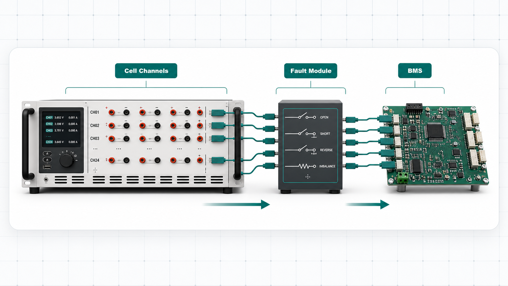
Emulate individual cell voltages, imbalance, balancing behavior, and fault states before connecting real battery strings.
- Cell voltage emulation for BMS inputs
- Open, short, reverse, and imbalance states
- Useful before real battery string validation
Short answer: a battery cell emulator is a multi-channel source that makes a BMS see controlled individual cell voltages. It is closely related to a battery cell simulator, but the word emulator is often used when the project needs precise reproduction of cell terminal behavior and abnormal states. Each channel independently sets a DC voltage that the BMS analog front end (AFE) measures as if it were a real cell, enabling repeatable validation of voltage sensing, protection thresholds, balancing algorithms, and fault detection logic without the safety hazards of physical cells.
Test scope
What a Battery Cell Emulator Does
Cell emulation is valuable when the BMS needs to be challenged with exact cell conditions rather than broad pack voltage alone. A cell emulator replaces each physical cell in a series string with a programmable voltage source, giving the BMS AFE precisely controlled inputs for every channel simultaneously.
Verify balancing commands, timing, current paths, and response to simulated cell imbalance. Set one channel 200 mV below its neighbors and confirm the BMS activates passive bleed or active transfer within the expected latency window.
Run open-wire, short, reverse, and mismatch cases repeatedly without risking real cell strings. Fault states can be triggered on a per-channel basis with deterministic timing, enabling statistical pass/fail analysis across hundreds of test cycles.
Terminology
Battery Cell Emulator vs Battery Cell Simulator
| Term | Typical meaning | Best use |
|---|---|---|
| Battery cell emulator | Precise reproduction of individual cell terminal behavior and fault states. | Cell-level BMS validation and edge-case testing. |
| Battery cell simulator | Broader equipment category for multi-channel cell voltage simulation. | Product comparison, test bench planning, and BMS workflows. |
| Battery pack simulator | Pack-level behavior rather than individual cell input channels. | High-voltage pack behavior, power electronics, and system validation. |
For a deeper comparison across all equipment categories, see the battery emulator vs simulator guide.
Channel architecture
Isolated vs Non-Isolated Channel Designs
The isolation architecture of a cell emulator determines how it connects to the BMS AFE and what series-string configurations it supports.
Isolated Channels
Isolated cell emulator channels have galvanic separation between each output and ground (and between adjacent channels). This allows every channel to float at a different potential within a high-voltage series string. In a 16S NMC pack where the top cell sits at approximately 67 V above pack negative, isolated channels ensure the emulator does not create ground loops or violate common-mode voltage limits. Isolation is typically implemented with reinforced transformers or optocoupled feedback paths, with ratings from 500 V to 1500 V per channel depending on the product.
- Required for series-string BMS validation where the AFE stack reference floats with cell position
- Prevents ground loops between emulator power supply and BMS measurement ground
- Supports daisy-chained AFE devices (e.g., multiple AFE ICs connected via iso-SPI or capacitively isolated interfaces)
- Enables testing of high-voltage packs (100S+ configurations) by cascading isolated modules
Non-Isolated Channels
Non-isolated channels share a common ground reference. They are suitable for single-cell AFE evaluation boards, bench-top prototyping with ground-referenced cell inputs, or cases where an external isolation barrier already exists in the test fixture. Non-isolated designs are typically lower cost and can offer faster voltage settling times since they avoid the bandwidth limitations of isolation barriers, but they cannot be stacked to emulate the upper cells in a series string without adding external differential amplifiers or isolation modules.
- Suitable for single-cell AFE evaluation and ground-referenced test setups
- Lower per-channel cost; faster voltage settling in some designs
- Cannot directly emulate upper cells in a series string without additional isolation
- Best paired with modular AFE development boards rather than full BMS hardware
| Characteristic | Isolated channels | Non-isolated channels |
|---|---|---|
| Series-string support | Yes — each channel floats independently | No — shared ground reference limits stacking |
| Common-mode voltage | Up to 1500 V per channel (product-dependent) | Limited to ground-referenced cells only |
| Ground-loop risk | None | Present — requires careful fixture design |
| Cost per channel | Higher (isolation magnetics, optocouplers) | Lower (direct DAC output) |
| Settling time | 10–100 µs typical (isolation bandwidth limited) | 1–10 µs typical (direct path) |
| Best application | Full BMS validation, multi-AFE stacks, production test | AFE eval boards, single-cell prototyping |
Imbalance simulation
How Cell Emulators Handle Imbalance
Cell imbalance is one of the most common failure modes in lithium-ion packs, and a cell emulator must reproduce it with sufficient resolution and speed to challenge BMS balancing algorithms.
Voltage Offset per Channel
Each emulator channel can be set to a voltage that deviates from the nominal value by a programmable offset. For example, in a 16S NMC pack where 14 cells are set to 3.7 V and two cells are set to 3.4 V, the BMS should detect the 300 mV imbalance and initiate balancing. The voltage resolution of the emulator (typically 1 mV or better) determines how precisely the imbalance can be controlled, which directly affects the accuracy of BMS threshold verification.
Programmable Imbalance Patterns
Advanced cell emulators support scripted imbalance patterns that evolve over time, simulating real-world divergence. Common patterns include: single weak cell (one channel offset low), progressive drift (one channel gradually decreasing over minutes or hours), step-change imbalance (sudden offset to simulate a cell with internal micro-short), and alternating imbalance (odd cells high, even cells low) to stress the AFE's differential measurement paths. These patterns can be triggered via SCPI commands or sequencer scripts, enabling automated regression testing of BMS firmware.
- Single-cell offset: test BMS detection of one weak or one strong cell
- Progressive drift: validate that balancing engages before the imbalance exceeds the safety threshold
- Step-change: confirm BMS response to sudden cell failure (internal short simulation)
- Multi-cell imbalance: stress AFE differential measurement across all inputs simultaneously
Fault injection
Fault Injection Capabilities per Channel
Fault injection is the primary differentiator between a cell emulator and a simple programmable power supply. Each channel must independently simulate fault conditions that the BMS must detect and handle.
Disconnects the channel output from the BMS AFE input, simulating a broken weld, disconnected bus bar, or failed cell interconnect. The BMS should detect the open condition within its specified sampling window (typically 100 ms to 1 s depending on ATE design).
Forces the channel output toward 0 V or a very low voltage, simulating an internal cell short. Used to verify that the BMS triggers under-voltage protection and sets the appropriate fault flag. Transition time from nominal to short state is typically programmable from <1 ms for hard shorts to >100 ms for soft shorts.
Drives the channel to a negative voltage (typically −0.5 V to −2 V), simulating a reversed cell connection. This tests the BMS ability to detect and flag reverse polarity before the AFE input protection clamps conduct, which is critical for manufacturing line testing where wiring errors are possible.
Fault Timing and Sequencing
In production test environments, fault injection must be deterministic and repeatable. Cell emulators achieve this through hardware-timed fault switching with microsecond-level resolution. A typical fault test sequence might set all channels to nominal, inject an open-wire fault on channel 7 for 500 ms, verify the BMS fault register, clear the fault, and proceed to the next channel. The entire sequence can be automated via battery simulator software using SCPI over Ethernet or USB, with pass/fail criteria defined in the test script.
| Fault type | Channel behavior | Typical timing | BMS expected response |
|---|---|---|---|
| Open wire | Output disconnected (high impedance) | Transition <10 µs | Open-wire flag, fault register set |
| Short circuit | Output driven to <0.1 V | Hard short <1 ms, soft short 10–200 ms | Under-voltage fault, disconnect contactor |
| Reverse polarity | Output driven to negative voltage | Transition <100 µs | Reverse-polarity flag, inhibit startup |
| BMS configuration | Series cells | Recommended channels | Notes |
|---|---|---|---|
| Low-voltage (4S–8S) | 4–8 | 8–12 | Single AFE; include spare channels for margin testing |
| Medium-voltage (12S–24S) | 12–24 | 16–32 | One or two AFE ICs; modular emulator preferred |
| High-voltage (48S–108S) | 48–108 | 48–120 | Multi-AFE daisy chain; cascaded emulator modules required |
| Energy storage (100S+) | 100–200+ | 100–200+ | Multiple cascaded units; master-slave synchronization needed |
Voltage Range Selection
The emulator voltage range must cover the full operating window of the cell chemistry, plus margin for fault conditions. LFP cells operate between approximately 2.0 V and 3.65 V, NMC cells between 2.5 V and 4.2 V, and some high-voltage chemistries reach 4.35 V or higher. A wide-range emulator (0–6 V) provides headroom for fault injection and supports multiple chemistries on the same instrument.
| Voltage range | Cell chemistry | Typical application |
|---|---|---|
| 0–3.6 V | LFP (LiFePO4) | Stationary storage, bus batteries, low-cost packs |
| 0–4.5 V | NMC, NCA, LCO | EV traction, consumer electronics, power tools |
| 0–6 V (wide range) | Multi-chemistry + fault margin | Test labs, contract manufacturers, mixed-chemistry programs |
Architecture mapping
BMS Architectures and Cell Emulator Configurations
Different BMS architectures impose different requirements on the cell emulator. Understanding the AFE topology determines the isolation, channel count, and communication interface needed.
Centralized BMS (Single AFE)
In a centralized architecture, a single AFE IC measures all cells in the string. This is common in 4S to 18S packs for e-bikes, power tools, and small energy storage systems. The cell emulator connects directly to the AFE cell input pins. Isolated channels are still recommended because the AFE reference may float relative to the emulator ground, especially in packs with a common ground-referenced load.
Distributed BMS (Daisy-Chained AFE)
Distributed architectures use multiple AFE ICs connected via isolated serial interfaces (iso-SPI, capacitively isolated UART, or transformer-coupled links). Each AFE measures a subset of the series string. The cell emulator must provide isolated channels across all AFE segments, ensuring that the common-mode voltage difference between the bottom AFE and top AFE does not exceed the emulator's isolation rating. For a 96S NMC pack using six 16-channel AFE ICs, the top AFE sits at approximately 400 V above pack negative, requiring 500 V or higher isolation per channel.
Modular BMS (Per-Module Controllers)
In modular architectures, each battery module has its own measurement and balancing controller that communicates with a central pack controller over CAN or iso-SPI. The cell emulator can test one module at a time (reducing channel count requirements) or test the full pack with cascaded emulator units. Modular testing is useful during module-level production verification, while full-pack testing is needed for system-level validation. See the BMS tester guide for system-level test approaches.
| BMS architecture | AFE count | Emulator isolation required | Typical channel count |
|---|---|---|---|
| Centralized | 1 | 500 V per channel recommended | 4–18 |
| Distributed | 2–8+ | 500–1500 V per channel | 16–144 |
| Modular | Per-module | 500 V per channel (module-level), 1500 V (pack-level) | 4–18 per module |
System comparison
Standalone Cell Emulator vs Integrated BMS Test Bench
Cell emulators can be deployed as standalone instruments or as components within an integrated BMS simulation bench. The right choice depends on test complexity, automation requirements, and budget.
| Criterion | Standalone cell emulator | Integrated BMS test bench |
|---|---|---|
| Setup complexity | Low — connect channels to BMS AFE inputs | High — integrate emulator, power supply, loads, CAN, temperature simulation |
| Test scope | Cell-level: voltage sensing, balancing, fault injection | System-level: includes current sensing, contactor control, thermal, communication |
| Automation | SCPI scripting via Ethernet/USB | Integrated test sequencer, HIL interface, production test framework |
| Cost | Lower — single instrument | Higher — multiple instruments plus integration engineering |
| Flexibility | High — can be repurposed across BMS platforms | Lower — typically configured for a specific BMS product line |
| Best for | R&D validation, AFE evaluation, early BMS firmware testing | Production line, acceptance testing, full system validation |
Many teams start with a standalone emulator during R&D and later integrate it into a production bench. Choosing an emulator with standard SCPI command support and modular channel expansion simplifies this transition. For guidance on building a complete test system, see the battery simulator test equipment overview.
Selection
Parameters to Compare
Match the BMS series-cell count and confirm whether channels need isolation. Verify the per-channel common-mode voltage rating covers the highest cell position in the string.
List the abnormal states that must be manually checked or automated. Confirm per-channel fault switching timing meets the BMS detection window requirements.
Decide whether the emulator must integrate with scripts, HIL tools, or production-like benches. SCPI command support and deterministic sequencing are essential for automated test flows.
Select a range that covers the cell chemistry operating window plus margin for fault conditions. Wide-range emulators (0–6 V) support LFP, NMC, and NCA on the same instrument.
Typical resolution is 1 mV or better. Higher resolution enables more precise threshold verification and smaller imbalance steps for balancing algorithm characterization.
Verify the emulator supports master-slave cascading for higher cell counts. Check synchronization between modules to ensure simultaneous voltage updates across all channels.
Workflow
Cell Emulator Test Workflow
A structured workflow ensures consistent BMS validation results across test cycles and team members.
- Define test matrix: Map every BMS threshold (OV, UV, OT, UT, imbalance, fault) to a specific emulator channel configuration and expected BMS response.
- Configure channels: Set per-channel voltages to the starting condition for each test case. Use the emulator software to save and recall channel presets.
- Execute test sequence: Step through voltage sweeps, imbalance injection, and fault scenarios using scripted SCPI commands or the built-in sequencer.
- Verify BMS response: Read BMS fault registers, balancing status, and protection outputs via CAN or direct register access after each test step.
- Log results: Record emulator settings, BMS responses, and pass/fail status for traceability and compliance documentation.
FaithTech paths
Product Directions
FT8330 Series
Multi-channel cell simulation for isolated cell-string tests and production validation paths. Supports 6 to 18 channels per module with cascading up to 144 channels.
FT8331 Series
Cell simulation with LFP and NMC voltage options, per-channel fault injection (open, short, reverse), and BMS validation workflows via SCPI over Ethernet.
FT8340 / FT8350 Series
Bidirectional behavior and balancing workflows for automated BMS benches. Supports active balancing current measurement and integrated production test sequencers.
FAQ
Battery Cell Emulator FAQ
What is a battery cell emulator?
It is a programmable multi-channel instrument that emulates individual cell voltages and abnormal cell states for BMS validation. Each channel independently sets a DC voltage that the BMS AFE measures as if it were a real cell, enabling repeatable testing of voltage sensing, protection thresholds, and fault detection logic.
When should I use a cell emulator instead of a pack simulator?
Use a cell emulator when the BMS must monitor many individual cell inputs. Use a pack simulator when the test target needs pack-level voltage and current behavior. Cell emulators excel at per-channel fault injection and balancing verification; pack simulators are better for power electronics and system-level integration testing.
Can a battery cell emulator replace real cells?
No. A cell emulator improves early validation and repeatable testing, but final safety and performance tests still require real cells or packs. Emulators cannot replicate real cell impedance dynamics under load, thermal behavior, or aging effects.
What is the difference between isolated and non-isolated cell emulator channels?
Isolated channels have galvanic separation between each channel and ground, allowing them to float at different potentials within a series string. This is required for testing BMS AFE stacks where the top cell may sit hundreds of volts above pack negative. Non-isolated channels share a common ground reference and are limited to ground-referenced single-cell testing or setups with external isolation.
How many cell emulator channels do I need for BMS testing?
Match the channel count to your BMS series-cell count. For a 16S BMS, you need at least 16 channels. Add spare channels if you want to test daisy-chain AFE stacking or expand to higher cell counts later. Modular emulators allow cascading for 32S, 48S, and beyond. For production test, consider whether you test full packs or individual modules to optimize channel utilization.
Can a cell emulator simulate cell imbalance conditions?
Yes. Cell emulators can program per-channel voltage offsets to simulate imbalance scenarios such as one weak cell in a series string, gradual divergence over time, or step-change imbalance to trigger BMS balancing thresholds. Advanced emulators support scripted imbalance patterns that evolve over time for automated regression testing of BMS balancing firmware.
Talk to FaithTech
Need a cell emulator for BMS testing?
Share your cell count, voltage range, isolation needs, fault cases, balancing type, and automation plan.