
Use models for SOC, temperature, voltage, and expected BMS state transitions. Software simulation is fast, repeatable, and useful for algorithm development and logic verification, but does not prove how the BMS hardware will respond to real electrical signals.
BMS simulation workflow
BMS Simulation
Model battery behavior, emulate cell and pack signals, inject faults, and validate BMS logic before real battery testing.
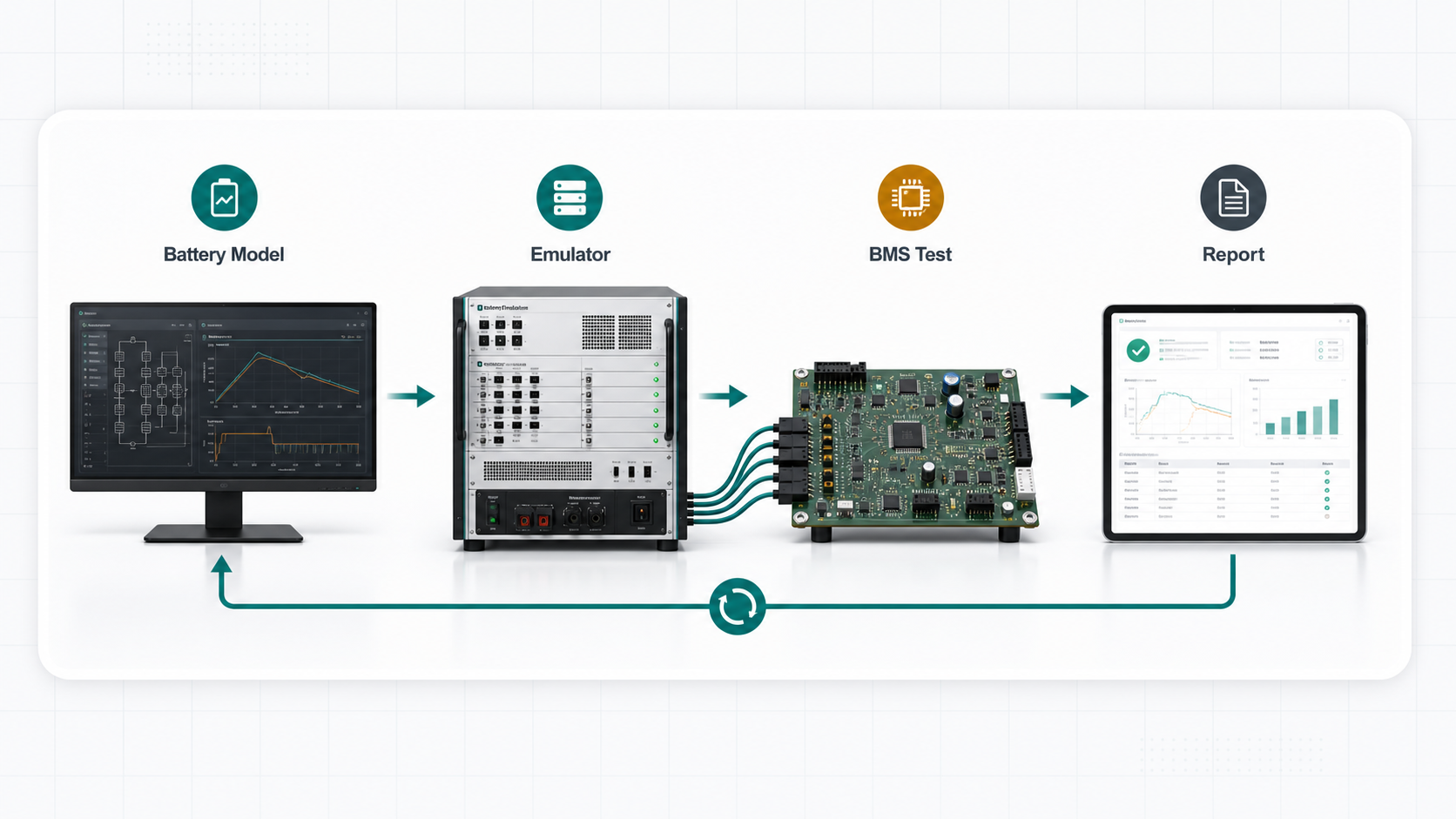
- Software models define expected behavior
- Hardware emulation presents measurable signals
- Real battery testing remains the final validation stage
Short answer: BMS simulation is the controlled validation path between pure software modeling and real battery testing. It can include battery models, cell emulators, pack simulators, fault injection, HIL benches, and reports that show how the BMS responds. The goal is to find logic errors, protection gaps, and communication problems early, when they are cheapest to fix, before connecting a live battery pack.
Meaning
What BMS Simulation Means
BMS simulation spans a continuum from pure software models to hardware-in-the-loop test benches. Each stage adds physical fidelity and reduces risk before real battery testing.
Use cell or pack emulators when the BMS must see real electrical inputs. Hardware emulation exercises the actual BMS sensing circuits, ADC paths, and protection drivers. It closes the gap between software correctness and hardware correctness.
Use real cells and packs after logic has passed controlled simulation and emulation tests. Real battery testing confirms thermal behavior, safety boundaries, and system-level integration that cannot be fully modeled or emulated.
| Stage | Best For | Speed | Cost |
|---|---|---|---|
| Software simulation | Algorithm development, state machine verification, parameter sweeps | Fast (milliseconds per step) | Low (software only) |
| Hardware emulation (HIL) | Sensing accuracy, protection timing, fault response, communication | Real-time | Medium (emulator hardware) |
| Real battery test | Thermal validation, safety boundaries, pack-level integration | Slow (hours per cycle) | High (cells, safety infrastructure) |
Comparison
Software Simulation vs Hardware Emulation vs Real Battery Test
Understanding the trade-offs between these three stages helps teams allocate testing effort and budget effectively. Most mature BMS validation programs use all three in sequence.
| Stage | What it proves | Limit |
|---|---|---|
| Software simulation | Logic, algorithms, state estimates, and expected behavior. | Does not prove electrical hardware response. ADC accuracy, comparator thresholds, and driver timing are not exercised. |
| Hardware emulation | BMS sensing, balancing, protection, communication, and fault handling with measurable signals. | Still controlled equipment, not a live battery pack. Thermal behavior and aging effects are not represented. |
| Real battery test | Final system behavior, safety boundaries, thermal behavior, and pack-level performance. | Higher setup time and risk; less convenient for repeated faults. Each fault test may damage cells or require safety intervention. |
Workflow
Typical BMS Simulation Workflow
A structured workflow ensures that each validation stage builds on the results of the previous one, reducing the risk of late-stage failures.
- Define the battery model. Choose cell chemistry, voltage range, SOC behavior, temperature assumptions, and boundaries. Document the model parameters so that the same reference is used across all simulation stages.
- Map the model to emulator signals. Convert model states into cell voltages, pack voltage, sensor inputs, and fault cases. Each software model state should have a corresponding emulator configuration that the cell emulator can reproduce.
- Run software-in-the-loop (SIL) tests. Verify BMS algorithms and state machines against the model in a pure software environment. Fix logic errors before investing in hardware test time.
- Run hardware-in-the-loop (HIL) tests. Connect the physical BMS to the emulator. Validate sensing accuracy, protection timing, balancing behavior, and communication under controlled conditions.
- Inject fault cases. Systematically test each fault mode (open circuit, short circuit, over-voltage, under-voltage, communication loss, temperature excursion) and verify that the BMS responds within specification.
- Review logs before real battery tests. Use pass/fail data from SIL and HIL stages to reduce risk before pack integration. All critical faults should be verified as handled before connecting live cells.
HIL testing
Hardware-in-the-Loop (HIL) Testing for BMS
HIL testing is the most common and effective form of BMS simulation for hardware validation. It connects the physical BMS to a real-time emulator that generates cell voltages, sensor signals, and fault conditions.
How HIL Testing Works
In a HIL test setup, the BMS under test is connected to a battery emulator instead of a real battery pack. The emulator receives commands from a test controller (typically a PC running test automation software) and generates the electrical signals that the BMS would see in a real pack. The BMS processes these signals through its normal sensing, protection, and communication paths, and its responses are logged and analyzed.
| HIL Component | Role | Example |
|---|---|---|
| Battery cell emulator | Generates per-cell voltages for BMS sensing inputs | FaithTech FT9350 integrated platform or FT8330 / FT8340 cell simulators |
| Pack voltage source | Supplies total pack voltage for BMS power input | Programmable DC supply (0–800 V) |
| Signal conditioning | Simulates temperature, current, and other sensor inputs | NTC simulator, current shunt emulator |
| Communication monitor | Records CAN, SMBus, or other bus traffic | CAN analyzer, protocol decoder |
| Test controller | Runs automated test sequences, logs results | PC with test automation software |
Benefits of HIL Over Pure Software Simulation
- Exercises the actual BMS hardware including ADC, comparators, and drivers
- Validates protection timing that depends on hardware response (not just software logic)
- Tests communication buses with real electrical loading and noise
- Supports fault injection that would damage real batteries (short circuit, over-voltage)
- Produces documented test results suitable for compliance reporting
When the bench also needs NTC temperature, total pack voltage/current, and fault signals in the same chassis, see the FT9350 comprehensive battery emulator.
Signals and faults
What to Include in BMS Simulation
A thorough BMS simulation covers electrical, environmental, and fault conditions. The scope depends on the BMS architecture and application, but the following categories are standard.
Include normal, boundary, imbalance, and transient states. Verify sensing accuracy across the full operating range, not just at nominal values.
Include sensor signals that affect protection and estimation logic. Temperature affects cell voltage and SOC estimation; current affects SOC drift and thermal management.
Include faults that must trigger safe BMS behavior and clear diagnostics. Each fault should be tested for detection time, response action, and recovery behavior.
Fault Injection Types and Test Objectives
| Fault Type | Description | BMS Response to Verify |
|---|---|---|
| Open circuit | One or more cell connections are disconnected | Detection within scan period; warning or contactor open |
| Short circuit | Cell input is shorted externally | Fast protection (<10 ms); contactor opens; fault logged |
| Over-voltage | Cell voltage exceeds safe maximum | Contactor opens; charging stopped; fault logged |
| Under-voltage | Cell voltage drops below safe minimum | Discharge stopped; warning or contactor open |
| Cell imbalance | Voltage difference between cells exceeds threshold | Balancing initiated; imbalance warning flag set |
| Communication loss | CAN or SMBus traffic is interrupted | Safe state entered within timeout; fallback behavior verified |
| Temperature excursion | Temperature signal exceeds safe range | Current limited or contactor opened; thermal management activated |
| Sensor drift | Temperature or voltage sensor reading drifts from actual | Detection and compensation or derating; accuracy check within tolerance |
FAQ
BMS Simulation FAQ
What is BMS simulation?
It is the process of modeling or emulating battery behavior so BMS logic can be validated under controlled conditions. BMS simulation can range from pure software models to hardware-in-the-loop test benches with real cell emulators.
Is BMS simulation only software?
No. It can start as software-only modeling, then move to hardware emulation using cell simulators, pack simulators, and BMS tester benches. Hardware emulation is necessary to validate sensing accuracy, protection timing, and communication.
Does simulation replace real battery tests?
No. It reduces risk and setup time before real battery testing, but final validation still needs real cells or packs. Simulation and emulation catch logic and protection errors early; real battery tests confirm thermal behavior and safety boundaries.
What is HIL testing for BMS?
Hardware-in-the-loop (HIL) testing connects the physical BMS to a real-time simulator that generates cell voltages, sensor signals, and fault conditions. The BMS responds as if connected to a real battery pack, but the test is fully controlled, repeatable, and safe.
What fault types should BMS simulation cover?
At minimum: open circuit, short circuit, over-voltage, under-voltage, cell imbalance, communication loss, and temperature excursion. Each fault should be tested for detection time, protection response, and recovery behavior. Additional faults depend on the BMS architecture and application.
How do I move from simulation to real battery testing?
Transition after model behavior, sensing, balancing, communication, and protection logic have all been validated under controlled emulated conditions. Review HIL test logs for any pass-with-issues results. Ensure all critical fault responses meet timing specifications before connecting live cells.
Talk to FaithTech
Planning a BMS simulation or HIL test path?
Share your model scope, BMS signals, cell count, pack voltage, fault cases, and automation requirements. FaithTech engineers can help configure the right simulation and emulation setup for your validation needs.