
Runs battery simulation functions including SOC-driven voltage profiles, pulse current steps, charge/discharge ramps, and static channel setpoints. The software translates a battery model (OCV-SOC curve, internal resistance parameters) into time-varying voltage and current commands sent to each hardware channel. On advanced systems, users can load custom OCV tables or select from pre-configured chemistry profiles for Li-ion, LiFePO4, NMC, and other cell types.
Automated test benches
Battery Simulator Software
Battery simulator software controls simulator hardware, runs SOC and sequence tests, triggers fault cases, and records data so BMS validation can be repeated and reviewed. Whether connecting a single battery cell simulator or orchestrating a multi-rack battery pack simulator system, the software layer determines how efficiently test engineers can build, execute, and analyze validation campaigns.
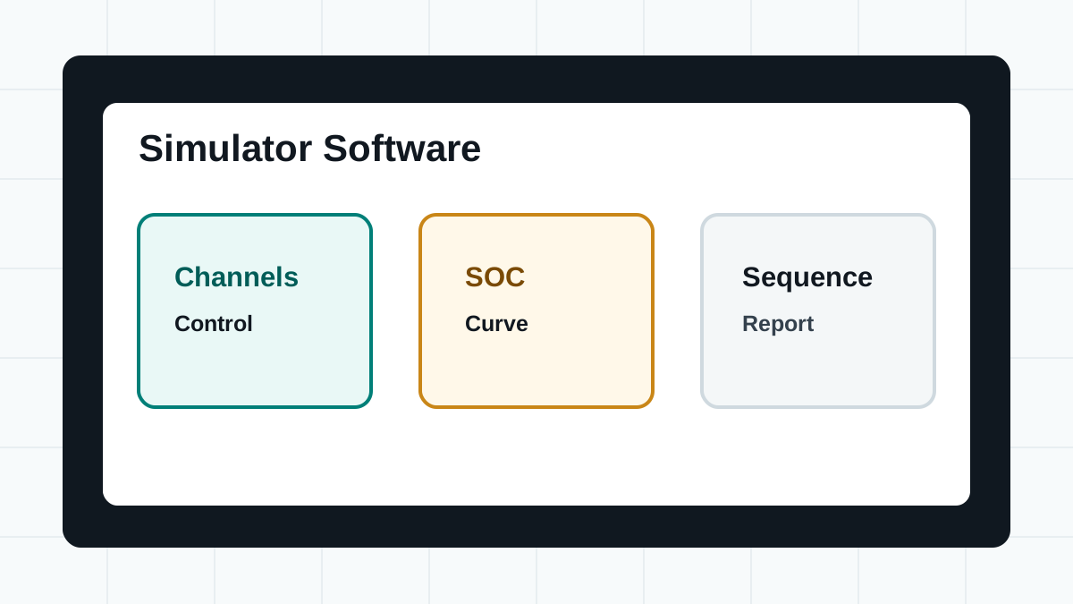
- Graphical interface for multi-channel control
- SOC simulation, sequence testing, and fault steps
- Remote interfaces such as SCPI and Modbus on supported systems
Short answer: while hardware generates the physical voltage and current, battery simulator software makes the test repeatable. It sets channel values, runs SOC or sequence tests, controls fault states where supported, and records data for review. It controls hardware modules such as battery cell simulators and pack-level test systems. Modern battery simulator software often exposes multiple control paths—a graphical upper-computer application for interactive bench work, and programmatic interfaces (SCPI, Modbus, or vendor SDKs) for automated test scripts. The software is the bridge between a test plan on paper and the thousands of data points collected during a validation run.
Core Functions
What Does the Software Manage?
Modern battery simulator software controls and monitors test cycles through four key functions that span the full BMS validation workflow, from initial channel setup through automated sequence execution to post-test data analysis.
Builds repeatable test steps for edge cases—over-voltage, under-voltage, cell imbalance, open circuit, short circuit, reverse polarity, and communication loss where supported. Sequences can branch based on measured values: for example, trigger a fault only after the BMS acknowledges a prior warning, or ramp voltage until the BMS opens its protection FETs while recording the exact trip point. This programmable fault injection replaces manual wiring changes and reduces human error.
Records channel voltage, current, temperature (where sensed), status flags, timestamps, and sequence step transitions into structured logs. Engineers compare the expected battery behavior (what the simulator was commanded to produce) against the BMS response (what the BMS measured and how it reacted). Discrepancies between these two data streams pinpoint calibration errors, threshold mismatches, or firmware bugs in the BMS under test.
Test Automation
Automating a Complete BMS Test Sequence
Manual channel adjustment is practical for quick bench checks, but production BMS validation demands automation. Below is a representative workflow for scripting a multi-cell BMS test from power-up through fault recovery.
Power on all simulator channels. Configure each channel with the target cell chemistry profile, voltage limits, and current limits. Set the initial SOC for each cell—typically all cells balanced at 50% SOC for baseline testing.
Step through a charge/discharge profile: ramp all cells to 4.2V (Li-ion full charge), hold, then discharge to 3.0V at a defined C-rate. The BMS should balance cells during charging and trigger under-voltage protection during deep discharge. Log all BMS-reported cell voltages against simulator setpoints throughout.
While maintaining all other cells at nominal voltage, program one channel to simulate over-voltage (above 4.25V), then under-voltage (below 2.5V), then an open-circuit condition. Verify that the BMS detects each fault within the specified response time and takes the correct protective action—typically opening charge or discharge FETs.
Create a deliberate imbalance: set half the cells to 4.15V and the other half to 3.85V. Enable the BMS balancing function and monitor whether the reported cell voltages converge over time. Measure balancing current and compare against the BMS datasheet specifications.
Return all channels to nominal values. Verify that the BMS re-enables charge/discharge paths after fault conditions clear. Generate a pass/fail report with timestamps for each event: fault injection, BMS detection, protection activation, and recovery. Export raw data in CSV or JSON format for traceability.
Software Architecture
Layers of Battery Simulator Software
Understanding the internal architecture helps integration engineers choose the right control path and debug communication issues. Most battery simulator software stacks follow a three-layer model.
The lowest layer handles physical transport: TCP/IP sockets for LAN-connected simulators, serial drivers for RS485 or CAN bus interfaces, and USB HID or VISA drivers for direct PC connections. This layer translates protocol-specific packets into a uniform command/response format used by higher layers. It also manages connection health—detecting timeouts, reconnection logic, and error retry policies.
The middle layer executes test sequences. It maintains the current state of every channel, steps through user-defined sequences (ramp, hold, pulse, fault injection), and evaluates conditional branches based on measured values. A robust sequence engine handles concurrent channel operations, ensuring that a 24-cell simulator updates all channels within the required timing window for the BMS sampling rate.
The top layer provides the graphical dashboard for interactive control and the reporting module for post-test analysis. It renders real-time channel status, plots voltage and current trends, and exports test data. On systems with programmatic APIs, this layer also exposes SCPI, Modbus, or SDK endpoints that external tools can call, treating the entire software stack as a remote-controlled instrument.
SCPI Command Reference
SCPI Commands for Battery Simulator Control
On simulators that support the Standard Commands for Programmable Instruments (SCPI) protocol over LAN or USB, test engineers can build scripts that programmatically control every channel. Below are representative SCPI command examples for common battery simulator operations.
| Operation | SCPI Command | Description |
|---|---|---|
| Set channel voltage | SOURce:VOLTage 3.700,(@1) | Sets channel 1 output to 3.700 V. |
| Set channel current limit | SOURce:CURRent 2.0,(@1) | Limits channel 1 output current to 2.0 A. |
| Enable channel output | OUTPut:STATe ON,(@1) | Turns on the output relay for channel 1. |
| Disable channel output | OUTPut:STATe OFF,(@1) | Turns off the output relay for channel 1. |
| Read measured voltage | MEASure:VOLTage? (@1) | Queries the actual output voltage at channel 1. |
| Read measured current | MEASure:CURRent? (@1) | Queries the actual output current at channel 1. |
| Set multiple channels at once | SOURce:VOLTage 3.700,(@1:12) | Sets channels 1 through 12 to 3.700 V simultaneously. |
| Query system status | SYSTem:STATus? | Returns the overall system status byte (OVP, OCP, OTP flags). |
| Load SOC profile | SOURce:FUNCtion:SOC "Liion_NMC_3p7V",(@1) | Assigns a pre-defined SOC profile to channel 1. |
| Trigger fault condition | SOURce:FAULt:OVERVOLTage 4.500,(@1) | Simulates an over-voltage fault of 4.500 V on channel 1. |
| Start sequence execution | SEQuence:STARt "bms_validation_v2" | Starts a pre-loaded test sequence by name. |
| Abort sequence | SEQuence:ABORt | Immediately stops the running sequence. |
| Reset to default state | *RST | Resets the instrument to power-on defaults (all channels off). |
In a Python or LabVIEW automated test script, these commands are typically sent over a VISA TCP/IP socket (TCPIP::192.168.1.100::5025::SOCKET). A Python example using PyVISA:
import pyvisa
rm = pyvisa.ResourceManager()
sim = rm.open_resource('TCPIP::192.168.1.100::5025::SOCKET')
sim.write('SOURce:VOLTage 3.700,(@1)')
sim.write('OUTPut:STATe ON,(@1)')
voltage = sim.query('MEASure:VOLTage? (@1)')
print(f'Channel 1 voltage: {voltage} V')
Modbus Register Map
Modbus Register Mapping for Battery Simulators
For integration with industrial PLCs and SCADA systems, selected battery simulators expose a Modbus TCP or Modbus RTU interface. The following is a representative register map for a simulator that supports register-based control.
| Register Address | Type | R/W | Description | Scale / Notes |
|---|---|---|---|---|
| 40001 | Holding | R/W | System control word | Bit 0: Output enable, Bit 1: Remote mode, Bit 2: Fault reset |
| 40002 | Holding | R | System status word | Bit 0: Output on, Bit 1: OVP active, Bit 2: OCP active, Bit 3: OTP active |
| 40010-40011 | Holding | R/W | Channel 1 voltage setpoint (float32) | IEEE 754, 0.0–5.0 V |
| 40012-40013 | Holding | R/W | Channel 1 current limit (float32) | IEEE 754, 0.0–5.0 A |
| 40014-40015 | Input | R | Channel 1 measured voltage (float32) | IEEE 754 |
| 40016-40017 | Input | R | Channel 1 measured current (float32) | IEEE 754 |
| 40018 | Holding | R/W | Channel 1 SOC setpoint | 0–10000 (0.00–100.00%) |
| 40020 | Holding | R/W | Fault injection register | 0: None, 1: Over-voltage, 2: Under-voltage, 3: Open circuit, 4: Short circuit |
| 40030 | Holding | R/W | Sequence control | 0: Stop, 1: Start, 2: Pause, 3: Resume |
| 40031 | Input | R | Sequence status | 0: Idle, 1: Running, 2: Paused, 3: Completed, 4: Error |
For multi-channel systems, the register map repeats in blocks. For example, channel 2 voltage setpoints may start at register 40050, channel 3 at 40090, and so on. Always consult the specific simulator's communication protocol manual for the exact register layout, as offsets and scaling factors vary between battery simulator test equipment models and manufacturers.
Data Management
Data Logging and Reporting
A BMS validation run on a 24-cell simulator sampling at 10 Hz generates over 2 million data points per hour. Structured logging and efficient export formats are essential for traceable, reviewable test results.
At minimum, log per-channel voltage setpoint, per-channel measured voltage, per-channel current, system status flags, sequence step number, and a UTC timestamp for every sample. For deeper analysis, also capture the BMS-reported cell voltages (read over CAN or isolated UART), temperature sensor readings, and any BMS fault codes. Comparing the simulator's commanded output against the BMS's measured input reveals gain errors, offset errors, and timing issues in the BMS analog front-end.
CSV is the most portable format—every analysis tool can read it. JSON is preferred when metadata (channel configuration, test parameters, operator ID) must travel with the data. Binary formats (HDF5, vendor-specific) are useful for high-speed logging where file size matters. Some software platforms support direct database insertion for integration with manufacturing execution systems (MES) where each battery pack's test record must be stored for regulatory compliance.
Post-test analysis typically involves overlaying commanded vs. measured voltage traces to identify BMS sampling errors, computing the time delta between fault injection and BMS protection response, and verifying balancing accuracy by comparing cell voltages after a balancing cycle. Automated report generation can produce a per-DUT pass/fail summary with highlighted anomalies, reducing the engineering time spent on data review from hours to minutes per test run.
Integration interfaces
Control Interfaces and Automation Paths
| Interface | Best fit | Typical commands |
|---|---|---|
| Upper computer software | Daily bench operation and visual control. | Single-channel programming, multi-channel editing, sequence tests, and data reporting. |
| SCPI | Remote instrument control where supported. | Set channels, read values, query status, and integrate into automated benches. |
| Modbus | Industrial control and automation integration where supported. | Exchange simulator status and commands with test systems. |
| LAN, RS485, CAN | Hardware communication interfaces on selected models. | Connect simulator hardware to R&D benches and automated test platforms. |
Third-Party Integration
Integrating with LabVIEW, Python, and MATLAB
Battery simulator software rarely operates in isolation. Most validation labs integrate it into broader test platforms. Below are the typical integration paths for the three most common engineering environments.
On simulators with SCPI support, the standard approach uses NI-VISA drivers to open a TCP/IP socket to the simulator and send SCPI commands as VISA Write/Read operations. Some vendors also provide native LabVIEW instrument drivers (`.lvlib` or `.llb` files) with pre-built VIs for channel setup, measurement, and sequence control. For simulators with Modbus interfaces, the NI Modbus Library provides Modbus master VIs that directly read and write holding registers.
PyVISA is the standard library for SCPI-based simulators, providing a consistent API across VISA transport layers (TCP/IP, USB, GPIB). For Modbus-based systems, the `pymodbus` or `minimalmodbus` libraries handle register read/write operations. Engineers often wrap these low-level calls in a Python class that models the simulator as an object with methods like `set_cell_voltage(channel, voltage)` and `read_all_channels()`. This abstraction layer lets the same test scripts control different simulator models by swapping the backend driver.
MATLAB's Instrument Control Toolbox supports both SCPI (via `tcpclient` or `visadev` objects) and Modbus (via `modbus` object). A common pattern loads battery model parameters (OCV-SOC curves from prior characterization data) into MATLAB, computes the required voltage profile for each test step, and then streams setpoints to the simulator using SCPI write commands. Measured data is pulled back into MATLAB arrays for immediate plotting and statistical analysis without intermediate file exports.
Deployment Models
Standalone Software vs. Integrated Platform vs. Cloud Control
The software environment for battery simulation falls into three deployment models, each with different trade-offs for BMS validation labs.
| Deployment model | Architecture | Best for | Limitations |
|---|---|---|---|
| Standalone upper-computer software | Windows application installed on a dedicated PC connected directly to the simulator via LAN, USB, or RS485. | Single-bench R&D labs where one engineer controls one simulator. Quick setup, no network dependencies. | No centralized data management. Each PC maintains its own test sequences and logs. Scaling to multiple simulators requires duplicating the setup. |
| Integrated test platform | The simulator software runs as a module within a larger test automation framework (e.g., NI TestStand, Vector CANoe, custom Python orchestration layer). | Production validation lines where the simulator must coordinate with other instruments—environmental chambers, CAN loggers, HIL systems, and MES databases. | Higher integration effort upfront. Requires clear API documentation and error-handling conventions from the simulator vendor. |
| Cloud-based or remote control | The simulator connects to a local gateway PC that bridges to a cloud platform via MQTT or REST APIs. Engineers access dashboards and run tests through a web browser. | Distributed teams or multi-site operations where test data must be accessible across locations. Enables remote monitoring of long-duration life-cycle tests. | Network latency can affect real-time control loops. Security considerations increase. Internet connectivity dependency is a risk for 24/7 test cells. |
Security
Security Considerations for Remote Battery Simulator Control
As battery test labs adopt networked simulators and cloud-based dashboards, the attack surface grows. A compromised simulator could inject false voltage readings into a BMS validation run, mask real faults, or damage connected hardware through unauthorized commands.
Place battery simulators and their control PCs on a dedicated VLAN or physically separate network segment. Do not expose simulator control ports (SCPI port 5025, Modbus port 502) to the corporate LAN or the internet without an authenticated gateway.
Where supported, configure IP whitelisting on the simulator so only authorized control PCs can send commands. For remote access, use SSH tunnels or VPN connections rather than direct port forwarding. Certificate-based authentication provides stronger protection than shared passwords.
Enable the software's command logging feature to record every voltage change, sequence start/stop, and fault injection event with timestamps and source IP addresses. Audit logs provide forensic evidence if a test result is questioned and help detect unauthorized access attempts.
Simulator firmware updates often patch security vulnerabilities in the embedded TCP/IP stack or web server. Maintain a firmware update schedule as part of lab asset management. Verify the integrity of firmware files using vendor-provided checksums before applying updates.
FaithTech features
FaithTech Software Environment
Control single channels or edit multiple channels simultaneously for BMS validation workflows. The graphical interface provides real-time voltage and current readback, color-coded status indicators per channel, and drag-and-drop sequence editing for building test procedures without writing code.
Use battery simulation, charge/discharge, pulse, sequence, and SOC-related functions on supported systems. FaithTech's simulation engine supports user-defined OCV-SOC tables, configurable internal resistance models, and temperature-dependent voltage compensation for accurate battery behavior replication.
Use professional testing software to support data reporting and engineering analysis. Export test data in CSV, JSON, or binary formats with automatic report generation that includes pass/fail summaries, waveform plots, and statistical comparisons between commanded and measured values.
FAQ
Battery Simulator Software FAQ
What does battery simulator software control?
It controls channel settings, battery simulation functions, sequence tests, pulse steps, fault states where supported, and data reporting. The software translates engineering requirements into hardware commands that set voltages, currents, and timing for each simulator channel.
Does FaithTech support remote control interfaces?
Selected FaithTech battery simulator models support interfaces such as LAN, RS485, CAN, SCPI, and Modbus. Confirm the exact interface for the target model. For automated test benches, SCPI over LAN is the most common remote control path, while Modbus is preferred for industrial PLC integration.
Is battery simulator software a standalone product?
Usually no. It is best understood as the control and automation environment for battery simulator hardware and test benches. The software is typically bundled with the hardware purchase, though some vendors offer SDKs and API libraries as separate downloads for custom integration projects.
What should I confirm before integration?
Confirm the simulator model, required communication interface, automation language, data reporting needs, fault cases, and whether the setup must integrate with a larger BMS test bench. Also verify the software's maximum channel count, sampling rate, and whether it supports the specific battery simulator fundamentals relevant to your chemistry and pack configuration.
What operating systems does battery simulator software support?
Most battery simulator upper-computer software runs on Windows (Windows 10/11). Some vendors provide Linux support, typically through cross-platform frameworks like Qt or through web-based interfaces that are OS-agnostic. For programmatic control with Python or MATLAB, operating system compatibility is usually determined by the VISA or Modbus library, both of which are multi-platform. Always confirm OS support for your target simulator model before procurement, especially for automated production lines that may run on Linux-based test controllers.
How do I protect test data when controlling a battery simulator remotely?
Use encrypted communication channels such as SSH-tunneled VISA connections or VPNs for remote SCPI access. Isolate the simulator control network from the corporate IT network using a dedicated VLAN or physical segmentation. Restrict access by IP whitelist or certificate-based authentication where the simulator supports it. Enable command audit logging to track every voltage change and sequence operation. Keep simulator firmware updated to patch vulnerabilities in embedded network stacks. For cloud-connected setups, verify that the cloud platform encrypts data both in transit (TLS 1.2+) and at rest.
Related guides
Related Emulation Topics
Talk to FaithTech
Need to integrate battery simulator software into your test bench?
Share your automation requirements, programming preferences, battery chemistry types, and hardware interfaces. FaithTech engineers can help map the right software drivers.