
Confirm that the BMS reads normal cells, weak cells, high cells, and boundary states correctly. The simulator can dwell at undervoltage and overvoltage thresholds for extended periods, allowing engineers to verify ADC accuracy, alert timing, and SoC estimation consistency across all monitored cells. A real pack cannot be held at a boundary condition indefinitely without risk.
BMS cell-level validation
Battery Cell Simulator
A battery cell simulator reproduces individual cell voltages and fault states so BMS teams can validate sensing, balancing, communication, and protection logic before connecting real battery strings.
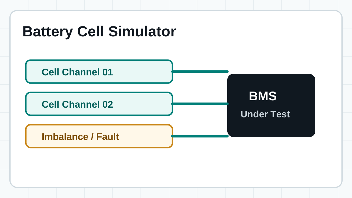
- Multi-channel isolated cell-string simulation
- Imbalance, open, short, and reverse fault cases
- Active or passive balancing validation workflows
Short answer: a battery cell simulator is used when the device under test needs to see many individual cell voltages rather than one pack output (which would require a battery pack simulator). This makes it especially useful for BMS validation, where the analog front-end (AFE) monitors every cell in the string independently. To understand the differences in terminology, check out our guide on battery emulator vs battery simulator. For a broader overview of how these tools connect to BMS test benches, see our BMS simulation guide.
How Cell Simulators Differ from Pack Simulators
Cell simulators and pack simulators address different layers of BMS testing. Choosing the wrong type creates gaps in validation coverage that real cells or packs may expose later.
A battery cell simulator provides multiple independent voltage outputs that represent individual cells wired in series — exactly the signals a BMS cell-monitoring unit (CMU) or analog front-end (AFE) expects at its sense inputs. Each output channel floats at its computed series potential, reproducing the stacked voltage profile of a real battery string. A battery pack simulator, by contrast, provides a single high-voltage output that represents the total pack potential and may incorporate pack-level current sourcing, precharge contactors, and isolation monitoring — functions needed at the system integration layer but invisible to individual cell-monitoring circuits.
When the BMS design requires per-cell voltage measurement, under-voltage and over-voltage detection per channel, and cell-level balancing validation, a cell simulator is the correct choice. Pack simulators are appropriate for validating overall system-level behavior such as contactor sequencing, insulation resistance monitoring, total pack voltage thresholds, and high-voltage interlock loop (HVIL) integrity. In a complete BMS validation strategy, the two instrument types are complementary: the cell simulator validates the AFE and cell-monitoring layer, and the pack simulator validates the system-level control and safety layer.
| Aspect | Battery Cell Simulator | Battery Pack Simulator |
|---|---|---|
| Output type | Multiple independent cell voltages | Single pack-level voltage |
| Channel count | 12–200+ isolated channels | 1–2 channels typically |
| Voltage range | 0–5 V per channel (cell level) | 0–1000 V (pack level) |
| Primary target | BMS AFE, CMU, cell monitoring | Pack controller, contactor logic, system integration |
| Balancing test | Per-cell passive and active balancing | Not applicable at cell level |
| Fault injection | Per-cell open, short, reverse, imbalance | Pack isolation, overcurrent, contactor fault |
| Typical use phase | Early BMS development and validation | System integration and HIL testing |
Workflow
What Engineers Can Test Before Real Cells
Cell simulation makes abnormal and edge conditions repeatable. That is the main value for BMS development — real cells degrade, drift, and introduce uncontrolled variables that make root-cause analysis difficult during firmware development.
Verify balancing commands, current paths, timing, and thermal assumptions before pack-level work. Passive balancing typically draws 50–200 mA per cell through bleed resistors — the simulator must source this current without voltage sag. Active balancing transfers charge between cells and requires a bidirectional simulator that can both source and sink current on each channel to validate charge-transfer logic.
Reproduce open wires, shorts, reverse states, and imbalance without damaging a real pack. Cell-level fault injection is deterministic and repeatable, enabling regression testing of BMS firmware updates against known fault patterns. Engineers can inject the same fault on the same channel across dozens of test cycles and expect identical BMS response timing — something no physical pack can guarantee.
Multi-Channel Architecture: Isolated Cell Channels
Cell simulators are built around independent, galvanically isolated channels that reproduce series-connected cell voltages without electrical interaction between channels.
Why Isolation Matters Per Channel
In a real battery pack, cells are physically separate units connected in series — each cell floats at a different potential relative to ground or chassis reference. A 12-cell series string with 3.6 V nominal cells places cell 1 at 3.6 V, cell 2 at 7.2 V, cell 3 at 10.8 V, and so on up to 43.2 V at the top of the stack. A cell simulator must reproduce this floating condition: each output channel must be galvanically isolated so that channel N can sit at N × 3.6 V without coupling noise or ground-loop currents into adjacent channels. Without galvanic isolation, the BMS AFE sees incorrect differential voltages, and the sense lines may carry unintended currents that damage the AFE input stage or distort measurements.
Independent Voltage and Fault Control Per Channel
Each channel in a multi-channel cell simulator is independently programmable. Engineers can set individual cell voltages anywhere within the supported range — typically 0–5 V or 0–6 V for lithium-ion chemistries — and can inject per-channel fault conditions including open circuits (disconnected cell tap, simulating a broken sense wire), short circuits (shorted cell or welded contactor), or reverse polarity. This granularity is essential for testing BMS detection thresholds: for example, setting channel 6 to 4.25 V while all other channels remain at 3.65 V verifies that the BMS correctly flags an over-voltage event on that specific cell without false-triggering on adjacent channels. Similarly, setting one channel to open while others remain at nominal voltage confirms that the BMS detects the missing cell tap and enters the appropriate fault state without misreading the voltages of neighboring cells.
Channel Count and Stacking Considerations
Select a simulator with at least as many channels as the largest cell string the BMS must monitor. Common configurations include 12, 24, 36, 48, and 96 channels — corresponding to typical pack architectures from small 12S modules up to large 96S battery packs used in energy storage systems. For production test environments, a single simulator unit can serve multiple BMS boards in parallel when channels are ganged, reducing test cycle time. When higher channel counts are needed beyond a single unit's capacity, multiple simulator units can be stacked via synchronization interfaces that maintain voltage accuracy and timing alignment across units. For guidance on selecting the right test equipment for your channel configuration, refer to our battery simulator test equipment overview.
Selection parameters
Battery Cell Simulator Parameters to Compare
| Parameter | Why it matters | Project question |
|---|---|---|
| Channel count | Defines how many series cells can be represented simultaneously. Insufficient channel count forces multiple test passes or limits the BMS configurations that can be validated in a single test run. | How many cells does the BMS need to monitor in the target pack configuration? |
| Isolation | Important for series strings and safe multi-channel operation. Galvanic isolation between channels prevents ground-loop errors and ensures each cell voltage floats at the correct series potential. | Do channels need independent galvanic isolation for series cell stack reproduction? |
| Voltage accuracy | Affects BMS threshold, calibration, and protection validation. The simulator should be at least 2× more accurate than the BMS AFE under test to provide meaningful pass/fail discrimination. | How tight are the BMS cell voltage measurement requirements? |
| Fault simulation | Lets engineers test abnormal states repeatedly without risk to real hardware. Per-channel fault injection must be independent so one fault does not affect adjacent channels. | Which open, short, reverse, and imbalance cases must be automated for regression testing? |
| Automation | Connects the simulator to scripts, logs, and production-like workflows via SCPI, Python, or CAN interfaces. Automated test sequences ensure repeatability and generate traceable test reports. | Will tests be manual, scripted, or part of an integrated bench system with CI/CD integration? |
Voltage Accuracy and Resolution Requirements for BMS Validation
Voltage measurement accuracy and resolution directly determine whether BMS protection thresholds can be validated with confidence. An inaccurate simulator creates false passes — or, worse, masks real BMS measurement errors.
Accuracy vs. Resolution: Understanding the Difference
Accuracy specifies how close the simulator's output voltage is to the commanded setpoint on an absolute basis — typically expressed as a percentage of reading plus a fixed offset in millivolts (e.g., ±0.02% + 1 mV). A simulator commanding 3.600 V with ±0.02% + 1 mV accuracy will output between approximately 3.598 V and 3.602 V. Resolution defines the smallest voltage step the simulator can produce (e.g., 100 µV or 1 mV). For BMS cell-monitoring validation, both parameters matter: accuracy determines whether the BMS ADC readings match a known cell state, while resolution determines whether the BMS can detect gradual drift, subtle imbalance buildup, or threshold crossings with sufficient granularity.
Calculating Required Accuracy for Your BMS
A typical BMS AFE specifies cell voltage measurement accuracy around ±2.5 mV to ±5 mV for lithium-ion cells. Industry best practice recommends the cell simulator be at least 2× more accurate than the device under test — so if the BMS AFE accuracy is ±5 mV, the simulator should deliver ±2.5 mV or better. At the 3.3 V to 4.2 V operating range common for lithium-ion cells, this corresponds to roughly 0.06% to 0.08% of reading. For higher-voltage chemistries such as LTO (1.5 V to 2.8 V), the absolute tolerance can be slightly wider in voltage terms, but the relative requirement remains constant since BMS protection thresholds are equally sensitive to percentage deviations.
Practical Accuracy Guidelines by Use Case
- ±1 mV accuracy or better — required for high-precision BMS calibration, research-grade cell characterization, and automotive functional safety validation (ASIL). These applications need the simulator to be a known, traceable reference.
- ±3 mV accuracy — sufficient for production BMS testing, standard development workflows, and most commercial battery management systems where the AFE specification is in the ±5 mV to ±10 mV range.
- 100 µV resolution — recommended when the BMS performs coulomb counting or SoC estimation based on fine voltage gradients, particularly for battery simulator software that models SoC from OCV look-up tables.
- Verify that accuracy specifications are maintained across the full operating temperature range of the test environment — some simulators derate accuracy outside 23 °C ± 5 °C.
FaithTech fit
Product Series to Review
For isolated multi-channel cell-string tests and production validation paths. Supports configurable channel counts for 12S through 48S BMS architectures with per-channel independent voltage programming and SCPI automation.
For cell simulation workflows that need voltage and fault simulation options. Adds per-channel open, short, and reverse fault injection capabilities for automated BMS protection validation and regression testing.
For bidirectional behavior, balancing workflows, and automated BMS benches. Channels can source and sink current, enabling both passive and active balancing validation within a single instrument — essential for production-grade BMS test systems.
Cell Simulation for Different Chemistries: LFP, NMC, and LTO
Each battery chemistry has a distinct voltage profile with unique flat regions, slope characteristics, and knee behavior. A cell simulator must correctly reproduce the voltage range and profile shape of the target chemistry for BMS algorithms to be validated against realistic cell behavior.
LFP (Lithium Iron Phosphate)
LFP cells operate in the 2.5 V to 3.65 V range with a notably flat open-circuit voltage (OCV) curve between 3.2 V and 3.35 V across most of the state-of-charge (SoC) window. This flat voltage characteristic demands high voltage resolution from the cell simulator — a 1 mV change may correspond to a 5–10% SoC shift in the flat region. When testing LFP BMS designs, configure the simulator with 0.1 mV resolution if available, and validate that the BMS SoC estimation algorithm does not drift during extended dwell periods in the flat region. The simulator must also accurately reproduce the sharp voltage rise at the top of charge (above 3.5 V) and the steep drop-off near full discharge (below 2.8 V), which are the regions where LFP protection thresholds typically trigger.
NMC (Nickel Manganese Cobalt)
NMC cells span 2.8 V to 4.2 V with a more sloped OCV profile that provides stronger voltage-to-SoC correlation than LFP. Simulators for NMC BMS testing must cover the full 2.5 V to 4.25 V range to test under-voltage and over-voltage protection thresholds with margin. The sloped profile means accuracy requirements can be relaxed slightly compared to LFP in the mid-SoC range, but fault injection at boundary voltages — 4.2 V for over-voltage warning, 4.25 V for over-voltage fault, 2.8 V for under-voltage warning — is critical for protection validation. Many NMC BMS designs also implement cell voltage spread detection; the simulator must be able to set individual channels at offset voltages while maintaining accurate voltage differences between cells.
LTO (Lithium Titanate)
LTO cells operate at a lower nominal voltage of approximately 2.3 V with an operating range of 1.5 V to 2.8 V. The cell simulator must support this lower voltage range while maintaining accuracy — some simulators optimized exclusively for the 3–5 V lithium-ion range lose precision or current drive capability below 2 V. Verify the simulator's accuracy specification at the low end of the voltage range (1.5 V), and confirm the channel hardware can deliver sufficient current for LTO cells, which often have higher charge and discharge rates due to their anode material properties. The wider voltage range between full charge and full discharge (as a percentage of nominal voltage) also means LTO BMS designs may have different balancing trigger logic than NMC or LFP systems. For more detail on simulator fundamentals across chemistries, see our battery simulator fundamentals guide.
Configuring a Cell Simulator for BMS Balancing Tests
Balancing validation requires the cell simulator to create controlled imbalance, maintain voltage setpoints while the BMS draws balancing current, and log the complete balancing timeline for analysis.
BMS balancing circuits — passive (dissipative, using bleed resistors) or active (charge-transfer, using DC-DC converters or switched capacitors) — activate when cell voltages diverge beyond a configured threshold. To validate this behavior with a cell simulator, the test must follow a controlled sequence that isolates the balancing function from other BMS behaviors:
- Create a known and measurable imbalance. Set one cell channel to a voltage above the balancing trigger threshold while all other channels remain at the nominal voltage for the target chemistry. For example, set channel 4 to 3.75 V with all other channels at 3.60 V for an NMC pack. The voltage delta should be large enough to exceed the balancing start threshold (typically 5–20 mV for passive systems) but not so large that it triggers an over-voltage fault instead.
- Maintain the voltage setpoint under load. During passive balancing, the BMS bleeds current from the high cell through a balance resistor — typically 50–200 mA depending on the BMS design. The simulator channel must source this current without allowing the voltage to sag, or the BMS may interpret the sag as balancing progress and stop prematurely. Verify the channel's source-current rating before beginning the test.
- Simulate balancing completion. After a defined balancing period or when the cell voltage falls below the balancing stop threshold, the BMS should deactivate the balance switch. The simulator should log the voltage-versus-time data and confirm the BMS stops balancing within the specified time window.
- Test multi-cell imbalance scenarios. Repeat the test with two or more cells simultaneously above the balancing threshold. Verify the BMS balances the correct cells concurrently without exceeding its thermal design limits, without timing conflicts between channels, and without incorrectly balancing cells that are at nominal voltage.
For active balancing tests with bidirectional simulators (such as FaithTech FT8340 and FT8350 Series), configure the low cell channels to accept charge from the balancer while the high cell channels source balance current. Bidirectional operation lets the simulator validate both charge-transfer directions — charge moving from high cells to low cells — in a single automated sequence. This is particularly important for systems that use active balancing to maximize usable capacity in large packs. For more on configuring automated test benches that include bidirectional instruments, see our battery simulator test equipment page.
Cell Simulator Test Workflow
A structured, repeatable workflow ensures consistent BMS validation results from bench setup through automated test execution and report generation.
-
Define the cell string configuration
Determine the number of series cells (e.g., 12S, 24S, 48S), the nominal voltage per cell for the target chemistry, and the sense-wire connection scheme required by the BMS AFE. Document the cell numbering convention — bottom-to-top or top-to-bottom — so it aligns with the simulator's channel assignment and the BMS monitoring software.
-
Wire the simulator to the BMS cell-sense inputs
Connect each simulator output channel to the corresponding BMS cell-sense input pair, following the pinout defined by the BMS hardware documentation. Verify all connections are secure and use the correct wire gauge for the expected balancing currents. Check that cell 0 (the most negative cell in the stack) is connected to the BMS reference as well as the corresponding simulator channel.
-
Configure baseline cell voltages
Program all channels to the nominal cell voltage for the target chemistry using the simulator's software interface or SCPI commands. Verify with an external calibrated DMM that each channel output is within the specified accuracy tolerance before connecting the BMS. Confirm the total stack voltage — the sum of all channel voltages — matches expectations.
-
Validate normal cell monitoring
Power on the BMS and confirm that all cell voltage readings from the BMS communication interface (CAN, SMBus, or SPI) match the configured simulator values within the BMS AFE accuracy specification. Log all readings for baseline reference and confirm no error flags are set during normal operation.
-
Run boundary and threshold tests
Step individual channels through under-voltage warning, under-voltage fault, over-voltage warning, and over-voltage fault thresholds. For each threshold crossing, measure the BMS response time and confirm it is within the specified limits. Test both rising and falling transitions to verify hysteresis behavior in the BMS firmware.
-
Execute the balancing test sequence
Create a controlled imbalance as described in the balancing configuration section. Trigger balancing, monitor voltage changes over time, and record which cells the BMS balances, the balancing duration, and whether post-balance voltages converge within the expected tolerance band.
-
Inject fault conditions on individual channels
Systematically test open-cell faults (simulating a broken sense wire), shorted-cell faults, and reverse-polarity conditions on individual channels. For each fault, verify the BMS enters the correct fault state, does not falsely trigger faults on adjacent cells, and exits the fault state correctly when the condition is cleared.
-
Automate the test sequence and generate reports
Convert validated manual test sequences into automated scripts using SCPI, Python, or the simulator's native automation framework. Generate test reports with pass/fail criteria for each test case, including timestamps, channel-by-channel voltage data, and BMS response metrics. Store test data for traceability, design review, and regulatory compliance submissions.
FAQ
Battery Cell Simulator FAQ
What is a battery cell simulator?
It is a programmable multi-channel source that reproduces individual cell voltages for BMS validation. Each channel independently generates a voltage representing one cell in a series string, with galvanic isolation between channels so the stack voltage accurately represents a real battery pack's cell-monitoring inputs.
Can it simulate a full battery pack?
It can simulate the cell-string inputs seen by a BMS analog front-end. Pack-level current, thermal behavior, contactor sequencing, and safety interlocks may require additional systems such as a battery pack simulator or hardware-in-the-loop (HIL) test bench. The two instrument types are complementary in a complete BMS validation strategy.
Why is isolation important?
Isolation helps reproduce series cell strings safely and avoids unwanted electrical interaction between channels. In a real pack, each cell sits at a different potential — cell 1 at 3.6 V, cell 2 at 7.2 V, cell 3 at 10.8 V, and so on. Galvanic isolation per channel ensures the simulator reproduces this floating potential profile without ground loops or cross-channel current paths that would corrupt BMS measurements.
Which FaithTech products should I review?
Review FT8330 for multi-channel cell-string simulation, FT8331 for simulators with integrated fault injection options, and FT8340/FT8350 for bidirectional operation supporting both passive and active balancing validation. Channel count, voltage range, accuracy class, and automation interface will determine which series best fits your project requirements.
What voltage accuracy is needed for BMS cell validation?
The cell simulator should be at least 2× more accurate than the BMS AFE under test. For a typical BMS with ±5 mV measurement accuracy, the simulator should provide ±2.5 mV or better. For high-precision BMS designs targeting ±1 mV cell measurement accuracy, the simulator should deliver ±0.5 mV accuracy with 100 µV resolution. Accuracy specifications must hold across the full operating temperature range of the test environment, and calibration certificates should be traceable to national standards.
How do you configure a cell simulator for balancing tests?
To configure a cell simulator for balancing tests, first set all channels to the nominal cell voltage for the target chemistry. Create a controlled imbalance by raising one or more channels above the BMS balancing trigger threshold — for example, set one channel to 3.75 V while others stay at 3.60 V for NMC cells. Ensure the simulator channels can source the full balancing current (50–200 mA for passive balancing) without voltage droop. Monitor cell voltages over time to verify the BMS activates balancing, maintains the correct balance current, and stops within the specified time window. For active balancing tests, use a bidirectional simulator such as FT8340 or FT8350 that can both source and sink current per channel.
Related guides
Next Topics
Talk to FaithTech
Need a battery cell simulator for BMS testing?
Share your cell count, voltage range, current range, fault cases, balancing type, and automation plan. FaithTech engineers can help match the right series.