
Drives individual cell voltage inputs to the BMS analog front end. Used to verify cell monitoring accuracy, balancing algorithm behavior, and per-cell fault detection thresholds. The cell simulator is essential in the first phase of BMS testing, where the goal is confirming that the BMS correctly senses and responds to each cell. See the battery cell emulator and BMS simulation guides for more detail.
Pack-level validation
Battery Pack Simulator
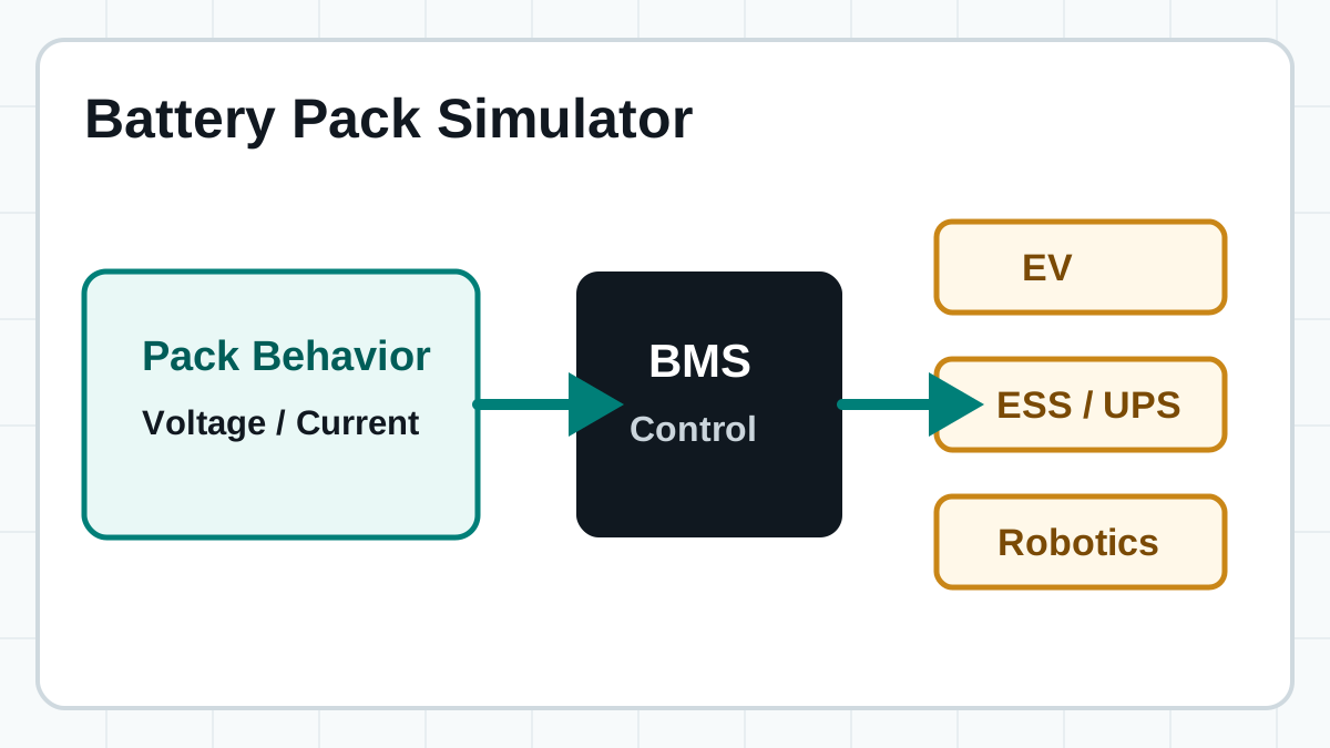
A battery pack simulator helps engineering teams reproduce pack-level voltage, current, and system response conditions for EV, ESS, UPS, robotics, and other battery-powered products.
- Pack-level behavior for system validation
- Useful after cell-level BMS checks
- Supports safer handoff to real battery testing
Short answer: a battery pack simulator reproduces the behavior of a complete battery pack as seen by a controller or system. It is useful when teams need pack-like behavior without starting every test with a real, high-energy battery pack. In earlier BMS testing phases, individual monitoring checks are typically performed using battery cell simulators, while overall equipment options can be reviewed in our battery simulator test equipment guide. Pack simulation becomes the logical next step once cell-level BMS functions are verified and the test objective shifts toward system integration and controller response validation.
Cell vs. pack
Pack Simulator vs. Cell Simulator
A battery cell simulator and a battery pack simulator serve different test objectives and operate at different points in the validation workflow. Understanding when each tool is appropriate avoids both under-testing and unnecessary complexity.
Reproduces the combined electrical behavior of the entire pack as seen by a system controller, inverter, or load. The test focus shifts from individual cell inputs to total pack voltage, pack current, contactor control, protection coordination, and state estimation at the system level. Pack simulation answers whether the system responds correctly to pack-level conditions.
Move to pack simulation after cell-level BMS functions are verified and the integration risk shifts to the system controller, contactor logic, load management, and protection chain. If the BMS still has unresolved cell-sensing or balancing issues, cell simulation remains the priority. Teams often run both in parallel: cell simulation for BMS firmware regression and pack simulation for system integration.
Voltage modeling
Pack Voltage Simulation
Pack voltage is the product of cell configuration and per-cell voltage. A simulator must reproduce not just the nominal pack voltage but the full operating envelope including transient behavior during load steps, regenerative events, and fault conditions.
Series and Parallel Configuration Effects
In a series configuration, total pack voltage equals the sum of individual cell voltages. A 96S lithium-ion pack with 3.7 V nominal cells produces approximately 355 V nominal, with an operating range from roughly 240 V at minimum SOC to 403 V at maximum SOC. The simulator must cover this entire range, including boundary conditions such as over-voltage and under-voltage fault thresholds that the BMS and system controller must detect.
Parallel cells increase pack capacity but do not change pack voltage. However, parallel connection introduces current-sharing behavior that affects pack-level response during high load transients. A pack simulator may need to model the effective internal resistance and time constants that result from parallel cell groups, especially when validating fast-charge or high-discharge scenarios.
Nominal and Boundary Ranges by Platform
| Platform | Configuration | Nominal voltage | Operating range |
|---|---|---|---|
| 48 V mild hybrid / telecom | 12S–16S | 44–59 V | 36–67 V |
| Low-voltage ESS | 16S | 59 V | 48–67 V |
| Passenger EV (400 V) | 96S–108S | 355–400 V | 240–454 V |
| Performance EV (800 V) | 192S–216S | 710–800 V | 480–907 V |
| Commercial EV / bus | Custom | 500–800+ V | Varies by configuration |
The simulator voltage range must cover not only normal operation but also the fault-detection thresholds that the BMS and system controller monitor. Under-voltage lockout, over-voltage protection, and insulation monitoring thresholds all require the simulator to drive voltages beyond the nominal operating window. For more on the underlying principles, see the battery simulator fundamentals guide.
Applications
Where Pack-Level Simulation Is Useful
Pack simulation is used across industries where battery-powered systems must be validated before committing to real battery testing. Each industry has specific test requirements that shape simulator configuration.
Validate vehicle controller response to pack voltage sag during acceleration, regenerative voltage rise, contactor pre-charge and disconnect sequences, and protection coordination between BMS and VCU. Test SOC estimation algorithms against modeled pack behavior before road testing. Specific requirements include transient response modeling for drive cycles and fault injection for over-current, over-temperature, and insulation failure scenarios.
Test battery-management paths for rack systems, UPS, and power continuity applications. ESS validation requires steady-state discharge profiles over extended durations, charge/discharge cycling behavior, and transition logic between grid-tied and backup modes. UPS testing focuses on switchover response time, voltage hold-up during load steps, and alarm thresholds for capacity degradation. Review related approaches in the battery simulator overview.
Validate how embedded systems respond to pack voltage, protection, and boundary behavior. Robotics applications require testing motor controller response during peak load events, protection coordination for stall conditions, and power-path management for multi-load systems. Power tool validation involves high pulse discharge behavior, thermal derating logic, and communication between the tool controller and the battery management IC.
Industry-Specific Test Requirements
| Industry | Key test focus | Typical pack voltage | Critical fault scenarios |
|---|---|---|---|
| Passenger EV | Drive-cycle transients, regen response, contactor control | 400 V | Insulation failure, over-current, crash disconnect |
| Commercial EV | Fast-charge profiles, thermal management, fleet cycling | 500–800 V | Connector arc, cell thermal runaway propagation |
| Grid-scale ESS | Long-duration cycling, rack-level balancing, grid response | 48–1500 V | Ground fault, rack communication loss, fire suppression trigger |
| UPS | Switchover time, voltage regulation, capacity alarm | 48–480 V | Unexpected discharge, charger failure, bypass failure |
| Robotics | Pulse load response, stall protection, power-path switching | 24–80 V | Motor over-current, communication timeout, thermal shutdown |
Recommended path
From Cell Emulation to Pack Validation
A structured validation path moves risk left: verify BMS cell-level functions first, then validate system-level pack behavior, and finally confirm with real battery testing. Each stage builds confidence before the next, reducing the chance of costly failures at later stages where debugging is more difficult and consequences are more severe.
| Stage | Goal | Equipment direction | Outcome |
|---|---|---|---|
| Cell simulation | Validate BMS sensing, balancing, and fault handling. | FT8330, FT8331, FT8340, FT8350 Series | Reduce early electrical and logic risk. |
| Pack behavior | Validate system response to pack-level conditions. | FT9350 Series comprehensive battery emulator and related BMS test benches | Prepare for system integration. |
| Real battery testing | Confirm safety, performance, and final boundaries. | FTS8500 and related battery safety systems | Move toward final validation with better preparation. |
Setup workflow
Pack Simulator Setup Workflow
Setting up a pack-level simulation bench requires coordination across electrical, software, and safety dimensions. The following workflow outlines the typical steps from initial requirements through operational readiness.
- Define pack electrical parameters: Specify nominal voltage, operating range, maximum current, number of series cells, parallel groups, and communication protocol (CAN, SMBus, etc.). Document the BMS architecture and identify which pack-level signals the controller expects.
- Select simulator configuration: Match the simulator voltage and current range to the pack envelope. Verify that the simulator can reproduce required transient response times and fault injection capabilities. Review options in the battery simulator test equipment guide.
- Integrate communication interfaces: Connect the simulator to the BMS and system controller via the required communication bus. Configure CAN messages, DBC files, or SMBus registers to match the production interface definition.
- Program test profiles: Load drive-cycle profiles, charge profiles, or custom load patterns. Define fault injection sequences for over-voltage, under-voltage, over-current, and communication loss scenarios.
- Verify safety interlocks: Confirm that emergency stop, over-temperature protection, and current limiting are operational before connecting the device under test. Validate that the simulator shuts down safely when interlocks are triggered.
- Run correlation checks: If available data from a real pack exists, compare simulator output against measured pack behavior to confirm that the model produces representative results within acceptable tolerances.
Key specifications
Pack Simulator Specifications
When evaluating a battery pack simulator for your test bench, the following specifications determine whether the instrument can meet your validation requirements. Not every specification is critical for every application, but understanding the full set helps avoid gaps during test execution.
The simulator must cover the full pack operating range from minimum SOC to maximum SOC, plus margin for fault thresholds. Voltage accuracy and resolution determine how precisely the simulator can reproduce cell imbalance effects at the pack level. For a 400 V pack, 0.1% accuracy means the simulator must be within 0.4 V of the target.
Pack current requirements vary from milliamps for quiescent current validation to hundreds of amps for drive-cycle or fast-charge profiles. Transient response time determines how quickly the simulator can follow load steps, which is critical for validating controller behavior during acceleration or regenerative braking events.
Some pack simulators provide a single combined output representing total pack behavior. Others offer multiple independent channels that can represent sub-pack sections or parallel paths. Multi-channel configurations are useful when testing modular pack architectures or redundant power paths.
List signal, communication, and automation interfaces needed for the bench. Common interfaces include CAN 2.0/CAN FD for automotive BMS, SMBus for smart batteries, and analog voltage/current outputs for direct sensor simulation. Ethernet or GPIB interfaces may be needed for automated test integration.
The simulator must be able to drive fault conditions including over-voltage, under-voltage, over-current, and open-circuit states. Fault injection speed and repeatability are important for testing protection response timing. Some simulators also support insulation fault simulation for high-voltage safety testing.
Support for scripted test sequences, automated regression runs, and integration with test management software reduces manual effort and improves repeatability. Look for API support, SCPI command sets, or dedicated test automation environments. See the battery simulator software guide for more detail.
Safety considerations
High-Voltage Pack Simulation Safety
Working with pack-level voltages introduces safety risks that cell-level testing does not present. Even though a simulator replaces the stored energy of a real battery pack, the simulator itself can source sufficient current at high voltage to create hazardous conditions. Safety planning must address both electrical hazards and test bench protection.
- Electrical safety: Pack simulators operating above 60 V DC present electric shock hazards. Follow applicable standards (IEC 61010, IEC 62477) for test bench insulation, grounding, and interlocked enclosures. All connections and disconnections must be made with the simulator output disabled.
- Current limiting: Configure the simulator current limit to the minimum value required for the test. This reduces the energy available during a fault and limits damage to the device under test if a wiring error or component failure creates a short circuit.
- Emergency stop: The test bench must have an accessible emergency stop that disconnects the simulator output and any auxiliary power. Verify that the emergency stop is functional and that all operators know its location before starting any test.
- Thermal monitoring: Monitor connections, cables, and the device under test for unexpected temperature rise. High-current connections that develop resistance due to loose terminals or corroded contacts can generate significant heat even at moderate currents.
- Isolation verification: Before connecting a high-voltage pack simulator, verify that the device under test has proper isolation from ground. Ground faults in the test setup can create unintended current paths that damage equipment or create shock hazards.
- Transition to real packs: When transitioning from simulation to real battery testing, ensure that the test bench safety infrastructure (containment, fire suppression, ventilation) meets the requirements for the real pack. The safety equipment needed for a simulated pack bench is typically insufficient for real battery testing. See the battery emulator circuit guide for circuit-level safety considerations.
What to define
Pack Simulator Requirements
Define nominal range, boundary range, transient needs, and expected operating envelope. Include both steady-state and dynamic requirements.
List signal, communication, and automation interfaces needed for the bench. Document which CAN messages, SMBus registers, or analog signals the controller expects.
Plan where simulation ends and real pack safety validation begins. Define the criteria that must be met before transitioning from simulated to real pack testing.
FAQ
Battery Pack Simulator FAQ
What is a battery pack simulator?
It is a system that reproduces pack-level battery behavior for a controller, BMS, or product under test. Unlike a cell simulator, which drives individual cell voltage inputs, a pack simulator provides the combined electrical behavior that a system controller or load sees from the complete battery pack. This includes total pack voltage, pack current capability, protection state signals, and communication bus behavior.
How is it different from a battery cell simulator?
A cell simulator focuses on individual cell inputs to the BMS analog front end. It verifies per-cell monitoring, balancing, and fault detection. A pack simulator focuses on the combined pack behavior seen by a system or controller, including total voltage, contactor control, and protection coordination. See the detailed comparison above.
Who uses pack simulation?
EV, ESS, UPS, robotics, power tools, drones, and other battery-powered product teams use pack simulation during development. Any team that needs to validate system-level response to pack behavior without the risk and cost of connecting a real high-energy battery pack is a candidate for pack simulation.
Can it replace real battery validation?
No. It helps teams prepare for real battery work by validating controller logic, protection coordination, and communication behavior in a controlled environment. Final safety, thermal, abuse, and performance testing still require real packs. Pack simulation reduces the risk and cost of real battery testing by catching integration issues earlier in the development cycle.
What voltage ranges do battery pack simulators cover?
Pack simulators cover ranges that depend on the target application. Common ranges include 48 V for low-voltage ESS and telecom backup, 400 V for passenger EVs, and 800 V or higher for performance EV and commercial vehicle platforms. The simulator must match or exceed the pack's nominal and boundary voltage envelope, including fault-detection thresholds.
When should a team move from cell simulation to pack simulation?
The transition typically happens after cell-level BMS functions (monitoring, balancing, fault detection) are verified using a cell emulator. Pack simulation becomes necessary when the test objective shifts from verifying BMS cell inputs to validating system-level behavior such as controller response, contactor control, load management, and protection coordination. Teams often run both in parallel during the transition period.
Related guides
Continue the Topic
Talk to FaithTech
Need a pack-level battery test path?
Share your pack voltage, current range, BMS architecture, application, safety requirements, and automation plan. FaithTech can help map the right validation path from cell simulation through pack integration to real battery confirmation.