FaithTech integrated BMS platform

FT9350 Comprehensive Battery Emulator

The FaithTech FT9350 brings cell and pack emulation, temperature signals, total voltage and current signals, and battery fault simulation into one modular 4U platform for BMS development and automated validation.

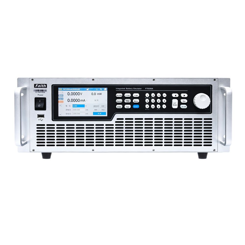
FaithTech FT9350 Series comprehensive battery emulator front view
  • Up to 39 mutually isolated independent channels
  • Up to 36 channels of NTC temperature simulation
  • Integrated cell, pack, fault, voltage, and current signals

Short answer: the FT9350 is designed for teams that have outgrown a cell-voltage-only simulator. Its modular architecture can combine battery simulation, temperature simulation, fault insertion, and pack-level voltage and current signals in one rack unit. This reduces the number of separate instruments and connections required to reproduce the signals a complete BMS expects during development and automated regression testing.

Core advantages

Why the FT9350 Is a Comprehensive Battery Emulator

The platform is built around signal coverage and integration. It combines the electrical inputs a BMS measures with the abnormal states its protection logic must detect.

Integrated signalsCell, temperature, pack voltage, and current

Build a more complete BMS input environment without assembling each signal type from a separate instrument.

Measurement0.01% F.S. voltage accuracy

Use high-precision voltage output with µA-level current measurement for sensing checks and static power-consumption tests.

AutomationLAN, RS485, CAN, SCPI, and Modbus

Integrate the unit into R&D benches or automated validation platforms while retaining standalone front-panel control.

Technical snapshot

FT9350 Capabilities at a Glance

Final channel and module selection depends on the requested configuration. These are the headline capabilities published for the FT9350 platform.

AreaPublished capabilityWhy it matters
Battery simulationUp to 39 mutually isolated independent channelsSupports series-connected cell signals without unwanted interaction between channels.
Integrated configurationUp to 33 cell-simulation channels with built-in fault simulationPlaces a high channel count and fault coverage in one standard rack chassis.
Temperature simulationUp to 36 channels, 0Ω to 16MΩ, up to 0.1% programming accuracyReproduces NTC thermistor inputs alongside the electrical cell signals.
Pack signalsOne voltage-simulation channel and one total-current signal channel in the integrated configurationLets the BMS compare individual cell inputs with pack-level measurements.
Fault simulationBattery disconnection, short circuit, reverse-polarity connection, and related fault statesExercises BMS diagnostics and protection responses without destructive live-battery fault creation.
Control and integration4U / 19-inch chassis, LAN, RS485, CAN, USB, SCPI, and ModbusFits standard test racks and supports both local operation and automated test control.

Product selection

Where FT9350 Fits in a BMS Test Strategy

The right choice depends on how many signal types the bench must reproduce, not only on channel count.

Test needProduct directionReason
Cell-voltage sensing and passive balancingFT8330 or FT8331 SeriesA focused cell simulator can be the simpler path when temperature and pack-level signals are handled elsewhere.
Bidirectional cell behavior and active balancingFT8340 or FT8350 SeriesBidirectional channels are the priority when energy must move in both directions during balancing tests.
Integrated BMS signal and fault validationFT9350 SeriesCombines cell, NTC temperature, total voltage, total current, and fault signals in one modular platform.
Real battery performance and safetyBattery cycler or safety test systemReal cells and packs remain necessary for chemistry, aging, thermal, and certification work.

Validation coverage

Tests the FT9350 Can Support

A comprehensive signal platform is most useful when the BMS response depends on several inputs changing together.

Normal operationCell and pack consistency

Present individual cell voltages, total pack voltage, and current signals together so the BMS can be checked for plausible and consistent measurements.

Environmental inputsTemperature-dependent behavior

Change simulated NTC resistance while cell and pack conditions evolve to verify derating, warnings, cooling requests, and shutdown logic.

ProtectionRepeatable fault sequences

Introduce disconnect, short, or reverse-polarity conditions and confirm detection time, diagnostic reporting, safe-state behavior, and recovery.

Bench planning

How to Define an FT9350 Configuration

Start from the BMS connector and test plan, then map each required signal to the appropriate module.

  1. List every BMS input. Record cell channels, thermistor channels, pack-voltage measurement, current-sensor signal, and any fault lines the bench must reproduce.
  2. Define electrical ranges. Specify the cell chemistry, maximum per-channel voltage, expected standby current, thermistor resistance curve, and pack-signal ranges.
  3. Prioritize fault coverage. Identify which disconnection, short, reverse, over-voltage, under-voltage, and temperature faults must be automated.
  4. Choose control interfaces. Match LAN, RS485, CAN, SCPI, or Modbus control to the existing automation environment and reporting workflow.
  5. Plan the real-battery handoff. Use the emulator for controlled functional and regression work, then reserve live cells or packs for the final thermal, performance, and safety stages.

FAQ

FT9350 Battery Emulator FAQ

What does the FT9350 comprehensive battery emulator integrate?

It combines battery cell and pack simulation with fault simulation, up to 36 channels of NTC thermistor temperature simulation, and mixed total-voltage and total-current signals. This makes it suitable for BMS benches that must coordinate multiple input types in one test sequence.

How many channels does the FT9350 support?

The platform supports up to 39 mutually isolated independent channels. FaithTech also describes an integrated configuration with 33 cell-simulation channels, 36 temperature-simulation channels, one voltage-simulation channel, and one total-current signal channel. The exact module mix should be confirmed for the target BMS.

What faults can the FT9350 simulate?

Published fault capabilities include battery disconnection, short circuit, and reverse-polarity connection. These controlled fault states help verify BMS detection, protection timing, diagnostic codes, and recovery without creating the equivalent dangerous condition on a live battery pack.

When should I choose FT9350 instead of a cell-only simulator?

Choose FT9350 when the same bench must coordinate cell signals, temperature inputs, pack-level voltage or current signals, and fault cases. If the project only needs cell-voltage sensing and balancing checks, a focused cell simulator such as the FT8330 or FT8331 may be the simpler option.

Does FT9350 replace real battery testing?

No. It is intended for controlled functional, diagnostic, and regression testing before live batteries are connected. Final chemistry-specific performance, aging, thermal behavior, and safety validation still requires real cells, packs, cyclers, and appropriate safety equipment.

Related guides

Plan the Complete BMS Test Path

Talk to FaithTech

Need an FT9350 configuration for your BMS?

Share the cell count, thermistor count, electrical ranges, fault cases, interfaces, and automation plan. FaithTech can confirm the right module combination.